| A | B |
|---|
Identify each of the geometric dimensions., 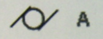 | cylindricity |
Identify each of the geometric dimensions.,  | profile of a line |
Identify each of the geometric dimensions., 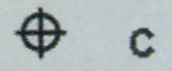 | position |
Identify each of the geometric dimensions., 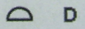 | profile of a surface |
Label the welding joints, 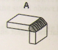 | corner weld |
Label the welding joints, 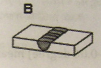 | butt weld |
Label the welding joints, 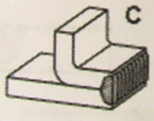 | edge weld |
Label the welding joints, 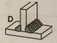 | T weld |
Label the section lining shown, 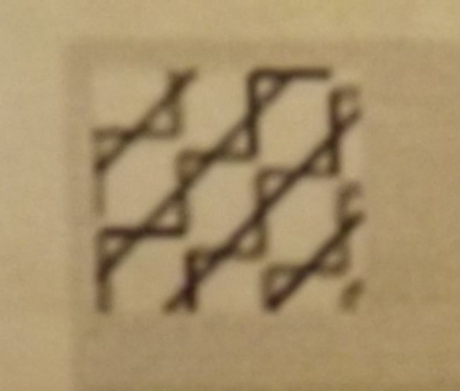 | thermal insulation |
Label the section lining shown, 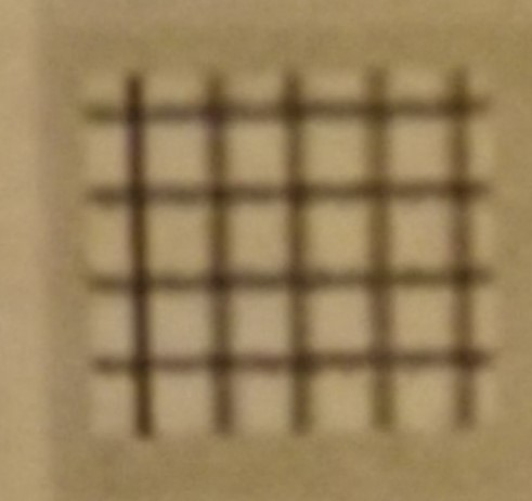 | electric windings |
Label the section lining shown, 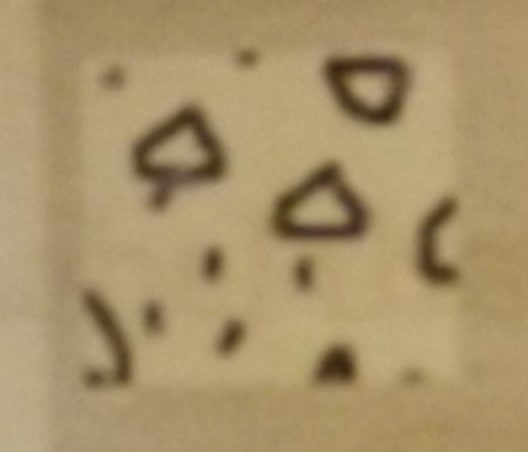 | concrete |
Label the section lining shown,  | aluminum |
Match the electrical symbols & the names,  | special purpose outlet |
Match the electrical symbols & the names, 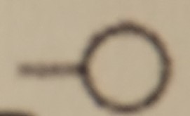 | wall outlet |
Match the electrical symbols & the names, 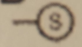 | pull switch |
Match the electrical symbols & the names, 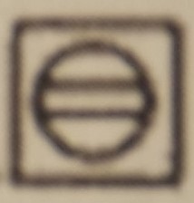 | floor duplex receptacle outlet |
Match the type of weld shown, 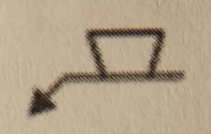 | plug or slot weld |
Match the type of weld shown, 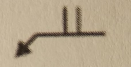 | square weld |
Match the type of weld shown, 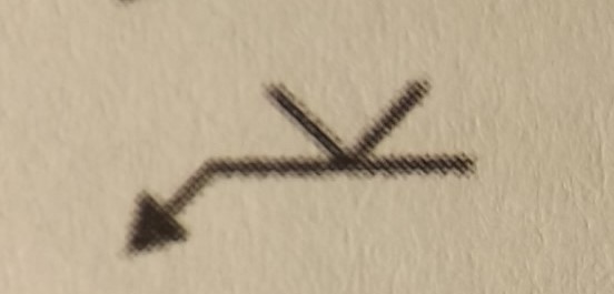 | V groove weld |
Match the type of weld shown, 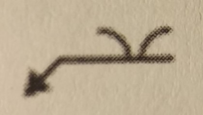 | flare V weld |
Label the groove joints shown, 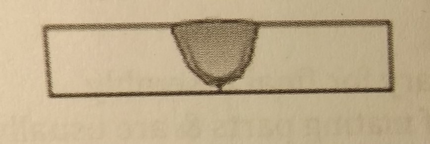 | single U groove joint |
Label the groove joints shown, 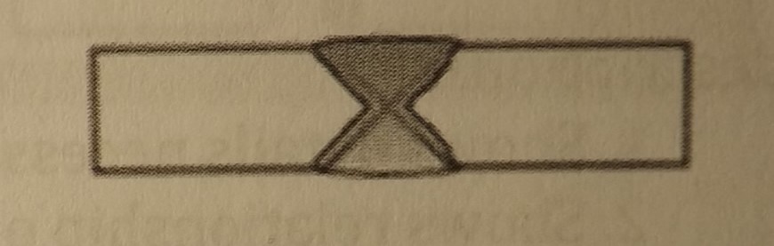 | double V groove joint |
Label the groove joints shown, 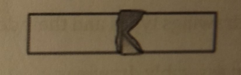 | double bevel groove joint |
Label the groove joints shown, 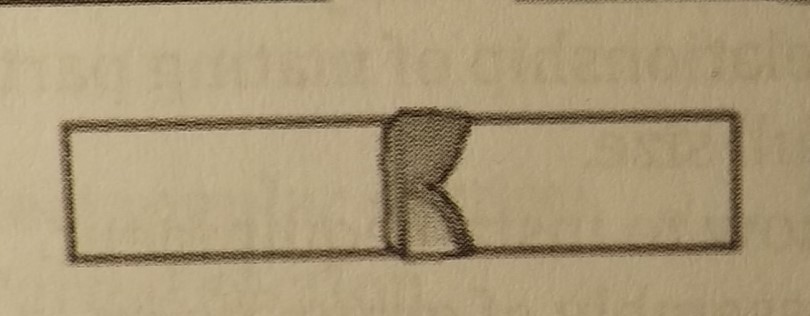 | double J groove joint |
| thick lines | object line |
| show relationship between lines | projections lines |
| long thin lines with short dashes between the segments | center lines |
| narrow lines | extension lines |
Label the architectural symbols shown, 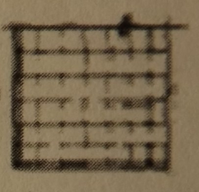 | ceramic tile |
Label the architectural symbols shown, 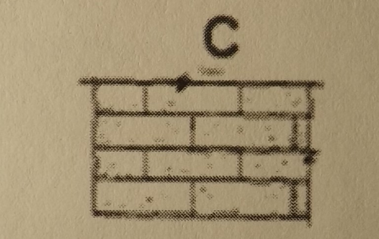 | concrete block |
Label the architectural symbols shown, 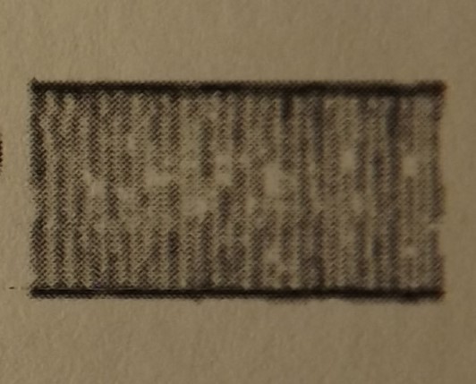 | sheet metal flashing |
| blueprint views that depicts a shaft shown horizontally | front & right side view |
| blueprint views that depict a shaft shown vertically | top & front view |
| common views depicting a three view blueprint | top, front, & right side views |
| group assembly drawings | shows assembly of group parts |
| design assembly drawings | show relationship of mating parts & are usually drawn full size |
| general assembly drawings | shows details necessary for final assembly |
| installation assembly drawings | shows how to install equipment |
Match the structured steel types and the symbols,  | structural T |
Match the structured steel types and the symbols, 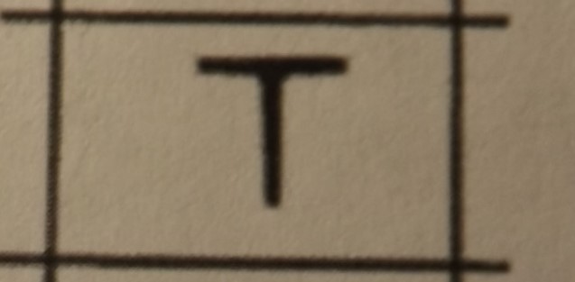 | T |
Match the structured steel types and the symbols, 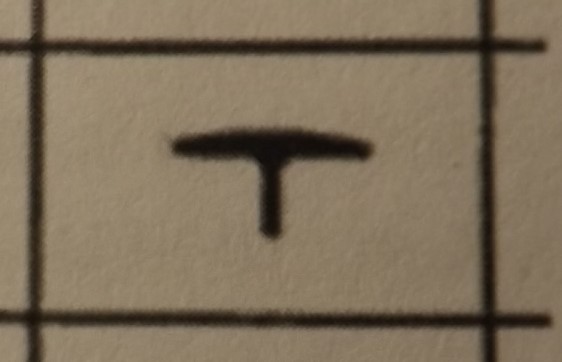 | Wall T |
Match the structured steel types and the symbols, 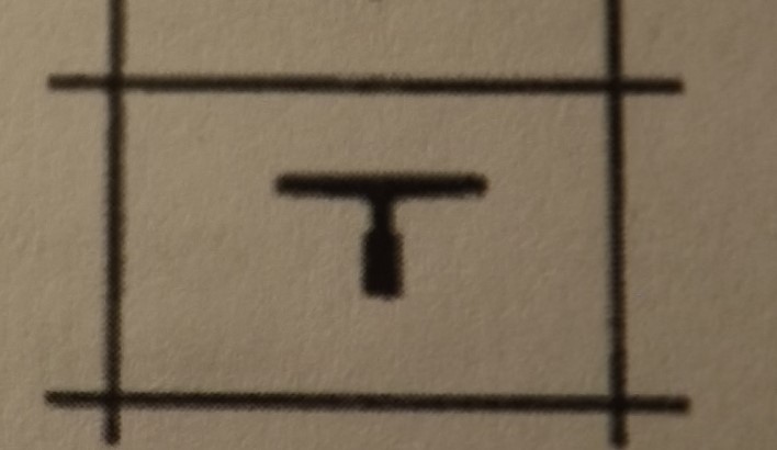 | Elevator T |
Label the HVAC symbols, 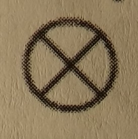 | automatic expansion valve |
Label the HVAC symbols, 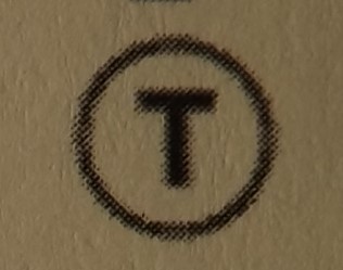 | self contained thermostat |
Label the HVAC symbols,  | compressor |
Label the HVAC symbols, 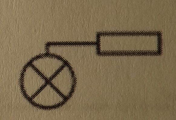 | thermostatic expansion valve |
Lable the break symbols shown,  | long breaks |
able the break symbols shown, 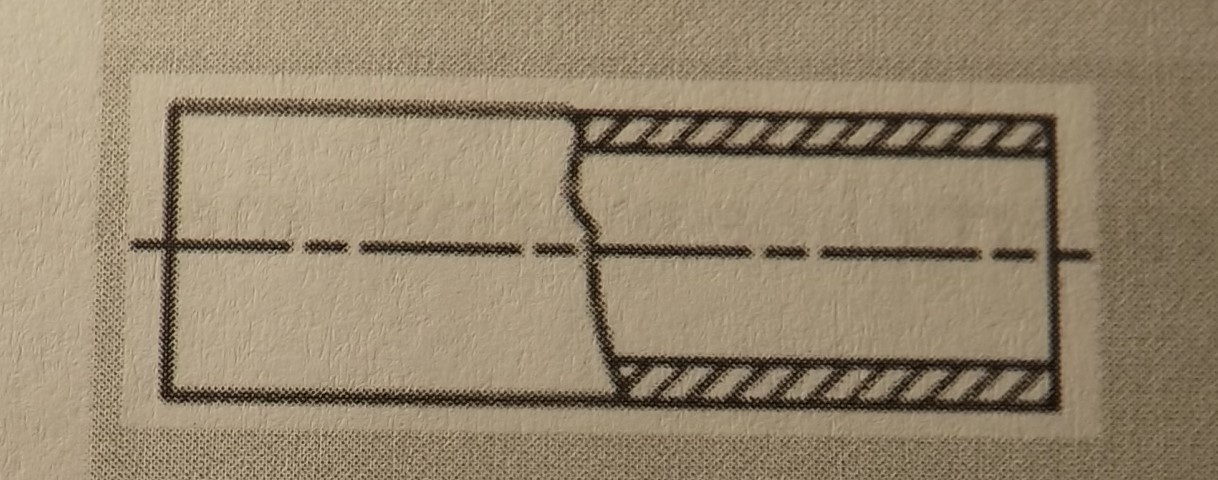 | partial section beak |
able the break symbols shown, 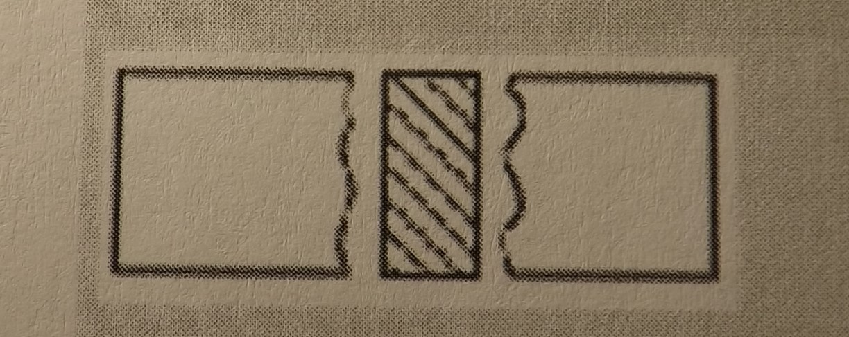 | rectangular section break |
able the break symbols shown, 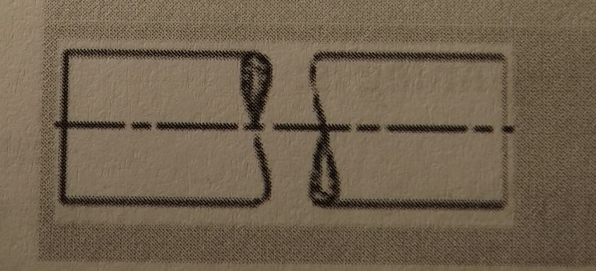 | round tubing section break |
| lay | orientation or machined surface |
| taper | surface of the frustrum of a cone |
| surface texture | random deviation from normal surface |
| surface finish | height limit of points on a machined surface |
Identify the minor diameter from the picture, 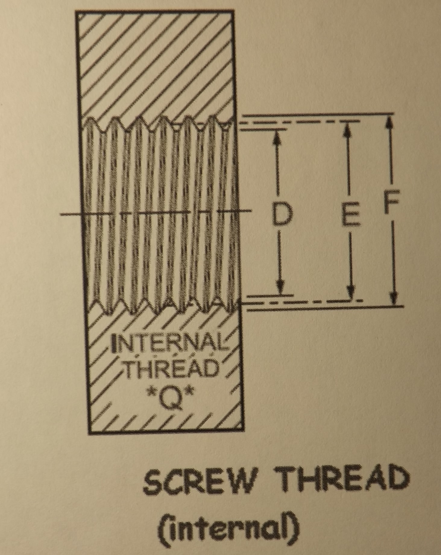 | D |
Identify the geometric dimensions shown, 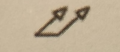 | total run out |
Identify the geometric dimensions shown, 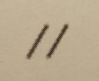 | parallelism |
Identify the geometric dimensions shown, 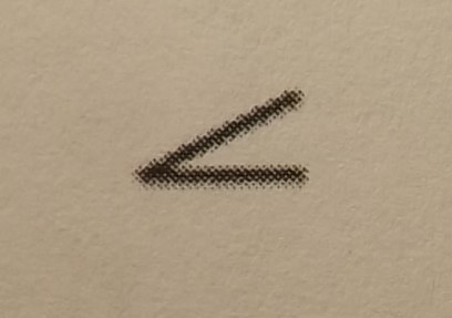 | angularity |
Identify the geometric dimensions shown, 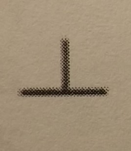 | perpendicularity |
Select the letter that shows thread runout,  | G |
| Select the letter that shows the pitch diameter, | B |
Label the contour lines in the graphic shown for A, 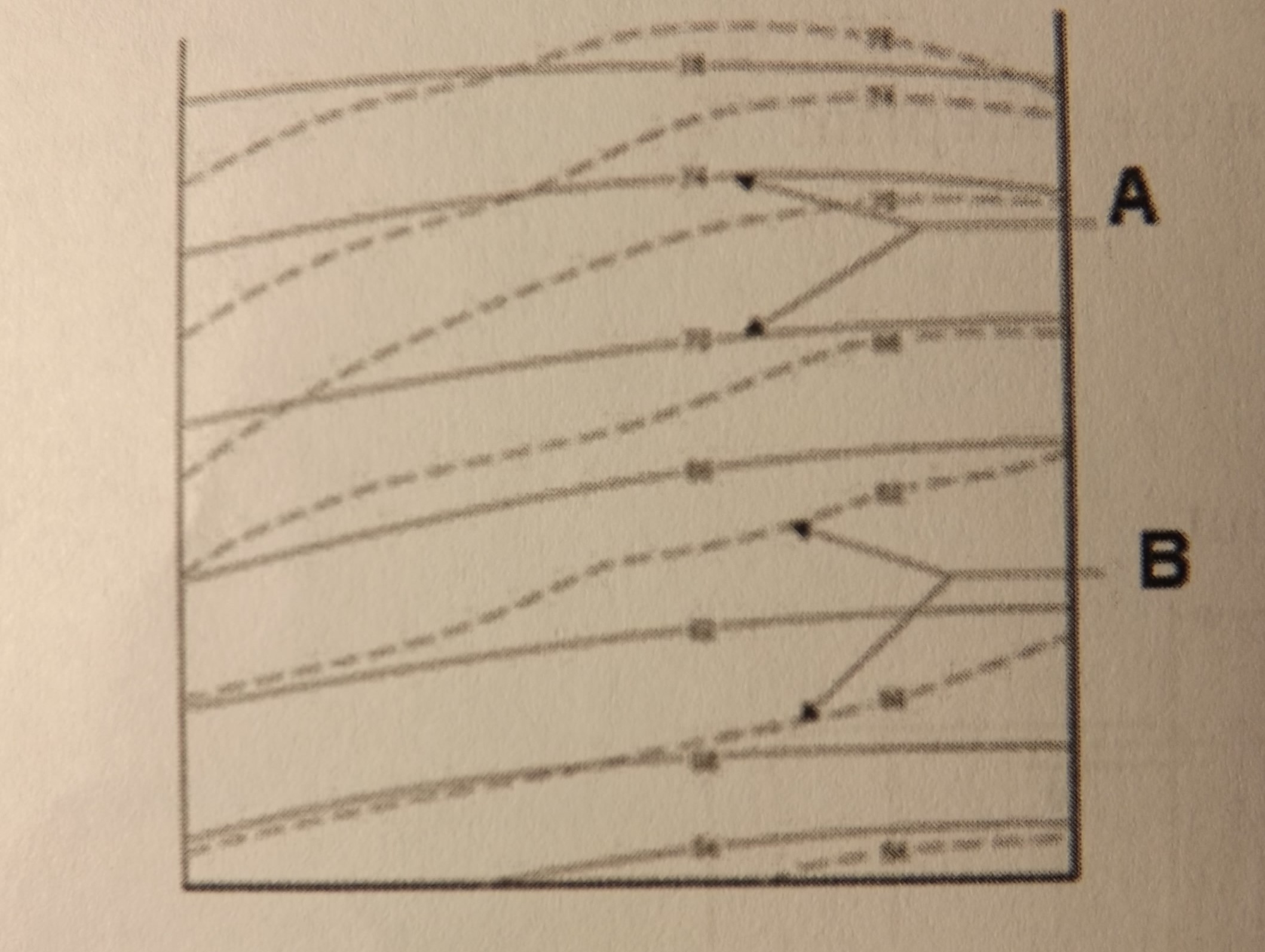 | finished grade |
| Label the contour lines in the graphic shown for B, | existing grade |