| A | B |
|---|
| 5 Unified Fabric Purposes | 1. Simplicity 2. Scale-Fabric Path (STP replacement) 3)Performance 4)Resiliency 5)Flexibility - setup in lots of architectures |
| 5 PARTS to Access - layer where we access stuff | 1.High availability 2.Convergence 3.Security 4.QoS a)Classification b)marking 5.IP Multicast |
| 6 Parts to Aggregation | 1.High Availability 2.Load Balancing 3.Routing - definitely or traditionally here a)Often where vlans terminate 4.QoS a)Queuing occurs here 5.FHRP 6.Security a)ACLs |
| Core | 1.Scalable 2.Speed, Speed and more Speed a)Move as quickly as possible 3.Less Devices - less cabling - less services |
| 4 7000 Sup1 | 1.No FCOE available on F2 module 2.No CPU sharing 3.4 VDCs - virtual device contexts 4. 32 FEXes no CMP - connectivity management processor |
| 4 7000 SUP2 | 1.FCOE 2.CPU Sharing 3.32 FEXes 4.4+1 VDC |
| 4 7000 SUP2E | 1.FCOE 2.CPU Sharing 3. 64 FEXes 4. 8+1 VDC |
| 5 M Series I/O modules | 1.NONE SUPPORT FCOE 2.VPC 3.QinQ 4.MPLS 5.OTV |
| 3 ALL M2 Support | 1.FEX 2.IEEE 1588 PTP (Precision Time Protocol) 3.PONG (improved ping utility) |
| ALL F Series I/O Modules | 1.Sampled Netflow 2.FEX 3.VPC 4.Fabric Path 5.L3 Interface 6.FCoE |
| Fabric Modules | 6.lossless throughput Virtual Ouput Queuing a)Fabric-1 Modules - 4.0 b)Fabric-2 Modules - 6.0 |
| 3 VRF COMMANDS - virtual routing and forwarding commands | 1)Show vrf 2)Show vrf management int 3)Show int mgmt 0 Ping 10.10.10.1 vrf management - ping from a valid vrf |
| 1000V - is a distributed virtual switch | 1.1000V ACI 2.1000V VMware VSphere 3.1000V Virtual Security Gateway 4.1100 Series Cloud Services Platform 5.1000V Microsoft Hyper-V 1000V InterCloud |
| 4 2000 Series FEXES | 5,6,7,9 |
| 3 2K 1G - no FCOE | 1. 2224TP - 24 RJ45 - Fabric Extender Interfaces - 2 2. 2248TP - 48 RJ45 - Fabric Extender Interfaces - 4 3. 2248TP-E - 48 RJ45 - Fabric Extender Interfaces - 4 |
| 3 2K 10G | 1. 2232PP - FCOE Support - Fabric Extender Interfaces - 8 2. 2248PQ - FCOE Support - Fabric Extender Interfaces - 8 3. 2232TM-E - FCOE Support - Fabric Extender Interfaces - 8 |
| VIC | virtual interface card plugs into the 2K from VM server so can ID the traffic |
| 3000 Series | with financial Services in mind - Top of rack Lowest possible latency |
| 4001I | created just for the IBM blade center H and HT chassis |
| 5000 | Layer 2 only - EOS modules |
| 5500 | Layer 3 allowed 5548P and 5548UP -Daughter card 5596UP and 5596T Expansion module |
| 9000 | ACI devices |
| 6000 | End of Rack a)High performance b)High Bandwidth Parents for FEXEs |
| 3 parts NXOS HA or Redundancy | 1. system manager 2. pss - persistent storage service 3. MTS message and transaction service |
| 3 system manager | 1. Launch stop and restart services on Nexus 2. Initiates switchover if needed 3. Monitored at kernel level using heartbeat |
| pss | persistent storage service - database on each sup - allows the stateful cutover in the event of a failover |
| mst | message and transaction service Mail carrier between all the components -Event notification and synchronizations |
| policy | informs the system manager when to reset it |
| show feature | shows installed features |
| ISSU | in service software upgrade - non-disruptive |
| 2 ISSU information | 1. began in 4.1 2. Control plane is not available but Data Plane is an active/passive supervisor most non-disruptive |
| 3 ISSU images to upgrade | 1. system 2. kickstart 3. fabric extender - 2k also is firmware |
| 3 Specfics to ISSU upgrade | 1. copy ftp://... bootflash://..... 2. copy bootflash:// - active to secondary 3. attach module x - used to confirm after copied |
| 2 Upgrade impact commands | 1. shows imcompatability system bootflash: - will configs be incompatable with config 2. show install all impact kickstart bootflash..... system bootflash - will it be non-disruptive - can you complete an ISSU |
| ISSU | install all kickstart bootflash:(new).... system bootflash:(new)....... |
| Verify ISSU upgrade | show ver - verify kickstart and bootflash: |
| 4 System Level HA | 1. redundant SUPs - active/standby stateful -. SSO - stateful switch-over 2. Fabric Modules - aka backplane - are redundant 3. Power Supply - redudant 4. Fan modules |
| 4 Supervisor Switchover | 1) Module failover - NSF - non-stop forwarding and SSO (stateful failover) 2)Admin initiated 3)Switch modules not reset 4)NO CMP reload |
| 2 Redundancy Commands | 1)Show sys redund status 2)System switch-over |
| system switchover | 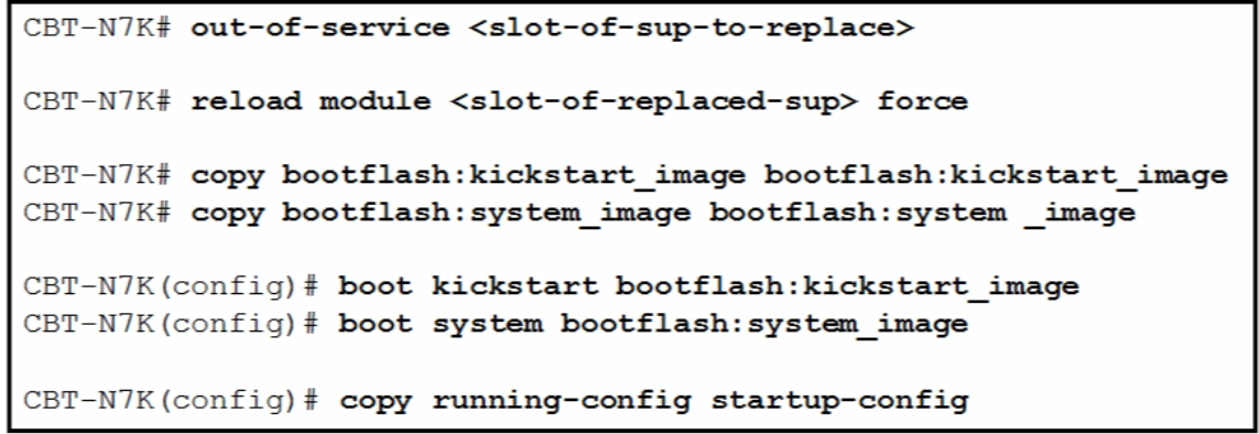 |
| 4 power redundancy modes | 1)Combined - No redundancy 2)Power supply redundancy (N+1) - Guards against failure of 1 device 3)Input source redundancy - grid redundancy - 2 different grids - Guards against failure of grid 4)Power Supply and input source redundancy (grid) i.Guards against failure of grid and one power supply as well ii.BEST one iii.DEFAULT REDUNDANCY MODE |
| VDC 1 in 6.1 | admin VDC, best practice not to use |
| 6 Default VDC | 1. CoPP 2. VDC resource allocation 3. NTP 4. Licensing 5. Software installation 6. Reloads |
| VDC resource types | 1. Global - boot image, ntp 2. Dedicated - port on I/O module 3. Shared - OOB ethernet management |
| VDC Controlling Resources | Can restrict Card types by VDCs i.Default is to only accept the M1 2) Resource template - set minimum and maximum NON-DEFAULT VDC 2. DEFAULT VDC |
| 2 SUPS and VDCs | 1.) SUP2 - 4 + 1 2.) SUP2E - 8 + 1 |
| default vdc config | 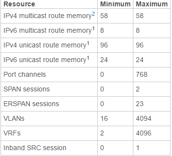 |
| non-default vdc config | 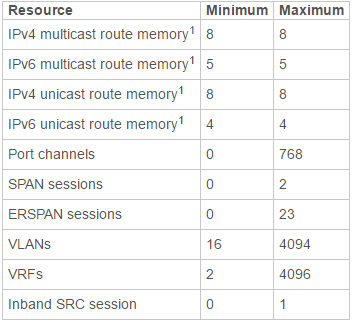 |
| 6 VDC Configuration | 1) Switchto - command you go into it and you have those same rights you have in the default VDC - switchback-switches back 2) Need Advanced Services Package - to run 3) MUST CREATE VDCs here 4) Allocate resources here NOTE PROMPT tell you which VDC you are in 5) Allocate physical resources i. Vdc VDC-B ii. (config-vdc)# allocate interface e2/1 6) Vdc mark <resource> i) No vdc mark - deletes it |
| VDC Verification Commands | 1) Show vdc 2) Show vdc detail 3) Show vdc membership - tells what int allocated to what VDC 4) Show vdc resource 5) Show vdc resource detail 6) Show vdc resource template TEST i. NOTE: MUST RE-APPLY TEMPLATE WHEN YOU MAKE CHANGES TO IT 7)Show start vdc-all 8) Show start vdc |
| 3 M2 Modules | 1.M224XP - 24 10 GE - SFP+ 2.M206FQ - 6 40 GE - QSFP+ 3.M202CF - 2 40/100 GE - CFP |
| Only these Fs support these 3 F2, F2e, F3 | 1. OTV 2. LISP 3. MPLS |
| 3 1100 Series Cloud Services Platform | 1.Piece of Hardware can run the Virtual Appliances 2.VSM - virtual switch module 3.VEM - virtual ethernet module - (like a fex) |
| 2 Auto-copy running (kickstart and system automatically copy) | 1.Show boot auto-copy 2.Show boot auto-copy list - shows that nothing is currently being copied at this time |
| HA Modes Single SUP | 1. bring down 2. restarts brings down and recreates the VDC |
| MA Mode DUAL SUP | 1. Bring down 2. Restart 3. SWITCHOVER - DEFAULT |
| Interface Types | 1. shared (default mode) - module specific 2. dedicated - only use one port |
| shared configuration | (config-if-range)# rate-mode shared |
| dedicated configuration | (config-if)# rate-mode dedicated |
| look for port group members what command do you use to get here | show interface e2/1 capabilities |
| Straight Thru with Static Pinning FEX config model | i. Straight through - FEX attaches to only one upstream parent device ii. Static pinning - server traffic is pinned to particular uplink |
| Straight Thru Static Pinning Configuration | 1. The ports are staticly pinned to the uplink ports a) So if the uplink goes down so do those servers i. Would multi-home to utilize other uplinks |
| Straight thru with dynamic pinning fex config | connection between the Nexus and FEX is through a port channel flows over one link in the bundle |
| Active/Active Fex config | uses VPC connects to multiple upstream devices through a vPC |
| fex verification command | show fex 111 |
| 5 fex configuration command | 1. feature fex 2. fex 111 3. interface e1/1 - 4 4. (config-if-range)# switchport mode fex-fabric 5. (config-if-range)# dex associate 111 |
| adapter FEX | 1. Done on Servers (vnic) a) Example Series i. UCS P81E (c series device) ii. Broadcomm 57712 2. Done on Nexus (5500 or 2k) (vethernet interface) 3. VNTag - is how traffic is tagged from vnic to vethernet interface NOTE: can do single-home but Active/Standby vnic - most redundant |
| 3 Basic Adapter FEX Install (auto-creation) | 1. Install feature-set virtualization 2. Feature-set virtualization 3. Vethernet auto-create |
| 7 Adapter FEX manual creation | 1) Dynamic interfaces are above 32769 so do below that 2) Interface vethernet 21 3) Bind interface e101/1/15 channel 1 4) Inherit port-profile user_data 5) Interface vethernet 21 6) Bind interface e101/1/15 channel 1 7) Inherit port-profile user_data |
| 7 Port-profile application steps | 1. Port-profile type vethernet USER_1 2. (config-port-profile)# switchport trunk allowed vlan 2-1000 3. (config-port-profile)# switchport trunk native vlan 2 4. (config-port-profile)# switchport mode trunk 5. (config-port-profile)# state enabled - how you turn on profile 6. Interface e1/15 7. (config-if)# switchport mode vntag - is the command used to connect to a server or the parent |
| 6 VLAN traits | 1) Are VDC specific 2) 1 - default cannot be deleted or modified 3) 2 - 1005 - normal 4) 1006 - 4094 extended vlans cannot be shutdown 5) Reserved vlans - varies 6) VTP - 5.1(1) later - server, client, trans, off i. Only v1 and 2 ii. UCS doesn’t support |
| Private VLAN config | b) Feature private-vlan c) Vlan 200 d) Private-vlan primary e) Vlan 300 f) Private-vlan community g) Vlan 400 h) Private-vlan isolated i) Vlan 200 j) Private-vlan association 300,400 k) Show vlan private-vlan l) Int ethernet 2/1 m) Switchport n) Switchport mode private-vlan host o) Switchport mode private-vlan host-association 200 (primary) 300 (secondary) p) Int e2/5 q) Switchport mode private-vlan promiscuous r) Switchport private-vlan mapping 200 300 |
| Default 7K spanning-tree | rpvst+ |
| MST Config | i. Spanning-tree mst configuration ii. (config-mst)# name MST-TEST iii. (config-mst)# revision 1 (note is 2nd part of name) iv. (config-mst)# instance 1 vlan 100 - 199 v. (config-mst)# instance 2 vlan 200 - 299 vi. (config)# spanning-tree mode mst vii. Show spanning-tree mst 1 |
| spanning-tree edge | same as portfast |
| spanning-tree network | has loopguard aka bridge assurance loss of bpdu from a networked port puts in inconsistent state |
| spanning-tree edge bpduguard default | sets bpduguard on - can also set globally with bpduguard config |
| port-channeling 7K - M moduule | 8 active 8 passive |
| port-channeling 7K F module | 16 active |
| port channeling 5K | 16 active |
| VPC Access Layer to Dual Uplink | 5K to 2 different 7ks - 2ks to 2 different 5ks |
| Dual Sided VPC configuration | aggregation layer vpc domain 2 - 7k access layer vpc domain 1 - 5k and 2K |
| Extended VPC single VPC domain all links active | 5500 - 2K dual to 55ks - c series etc - dual vNICs |
| 4 LACP configuration | 1) Feature LACP (to turn one) 2) (config-if-range)# Channel-group 2 mode active 3) (config)# interface port-channel 2 4) (config-if)# switchport access vlan 10 |
| 4 LAG (non-LACP config) | 1) Int e2/1-4 2) (config-if-range)# channel-group 1 3) (config)# interface port-channel 1 4) (config-if)# switchport mode trunk |
| 4 L3 Port channel | 1)Int e2/5-7 2)(config-if-range)# channel-group 3 3)(config)# interface port-channel 3 4)(config-if)# ip address 10.10.1.1 255.255.255.0 |
| Port Channel Verification Commands | 1. show port-channel summary 2. show port-channel load-balance |
| Port channel load balancing | Port-channel load-balance ethernet ? |
| VPC config 5 parts | 1. vpc domain 2. vpc peers 3. vpc member ports 4. vpc link |
| vpc domain | logical ID for all within vPC |
| peer link (vpc) definition | creates illusion of single device |
| 6 vpc peer link traits | 1.Control traffic 2.Forwards data a) Flooded traffic i. Multicast ii. Broadcast iii. Unknown unicast 3. Sync mac-tables 4. Orphan ports a) Does not want to participate b) Looses member ports so orphans 5. Can carry HSRP if it is L3 6. CFS - Cisco Fabric Services (so peer links can communicate) a) Need to sync it |
| Peer keep-alive lin | no data or sync is secondary check to config VPc is healthy |
| 7 VPC Link | i. Peer link 10Gps ii. Cannot do secondary keep-alive over peer-link iii. Per VDC context config iv. Same devices in VPC v. Only one vPC domain per switch or VDC vi. Some not support L3 vii. Static routing to FHRP |
| vpc config beginning commands | i. Feature vpc ii. Vpc domain 10 (can be 1 - 1000) - best practice use unique ID VPC system-mac includes domain ID iii. (config-vpc-domain)# peer-keepalive destination 192.168.1.2 Source 192.168.1.1 vrf VPC-KEEPALIVE 1. Defaults to mgmt vrf (OOB) but can config elsewhere 2. Best practice to not use peer-link |
| vpc config interface commands | 1. interface po7 2. (config-if)# vpc 7 |
| this vpc domain command will send the information out the interface if it arrives there even if it is not the FHRP gateway if FHRP gateway is within vpc domain | (config-vpc-domain)# peer-gateway |
| this vpc domain command with set both in the VPC to be the root switch | (config-vpc-dmain)# peer-switch |
| dynamic pinning | 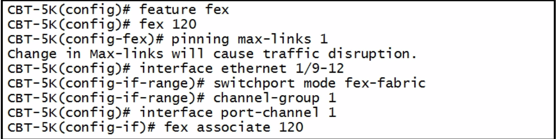 |
| active-active pinning | 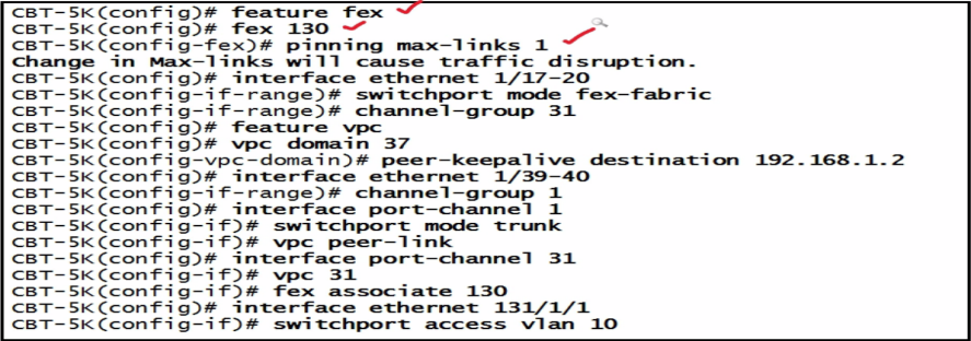 |
| enhanced vPC | 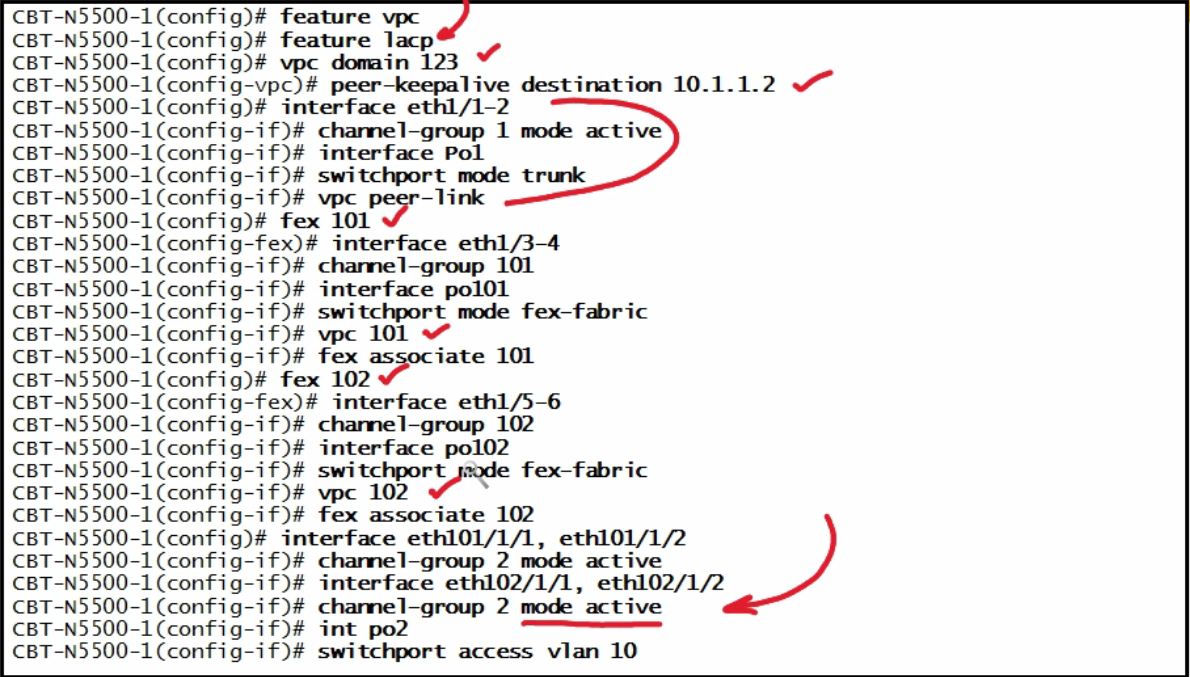 |
| all pinning examples | 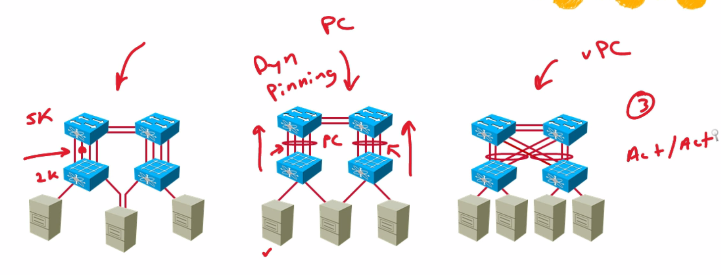 |
| vdc resource config conmmands | 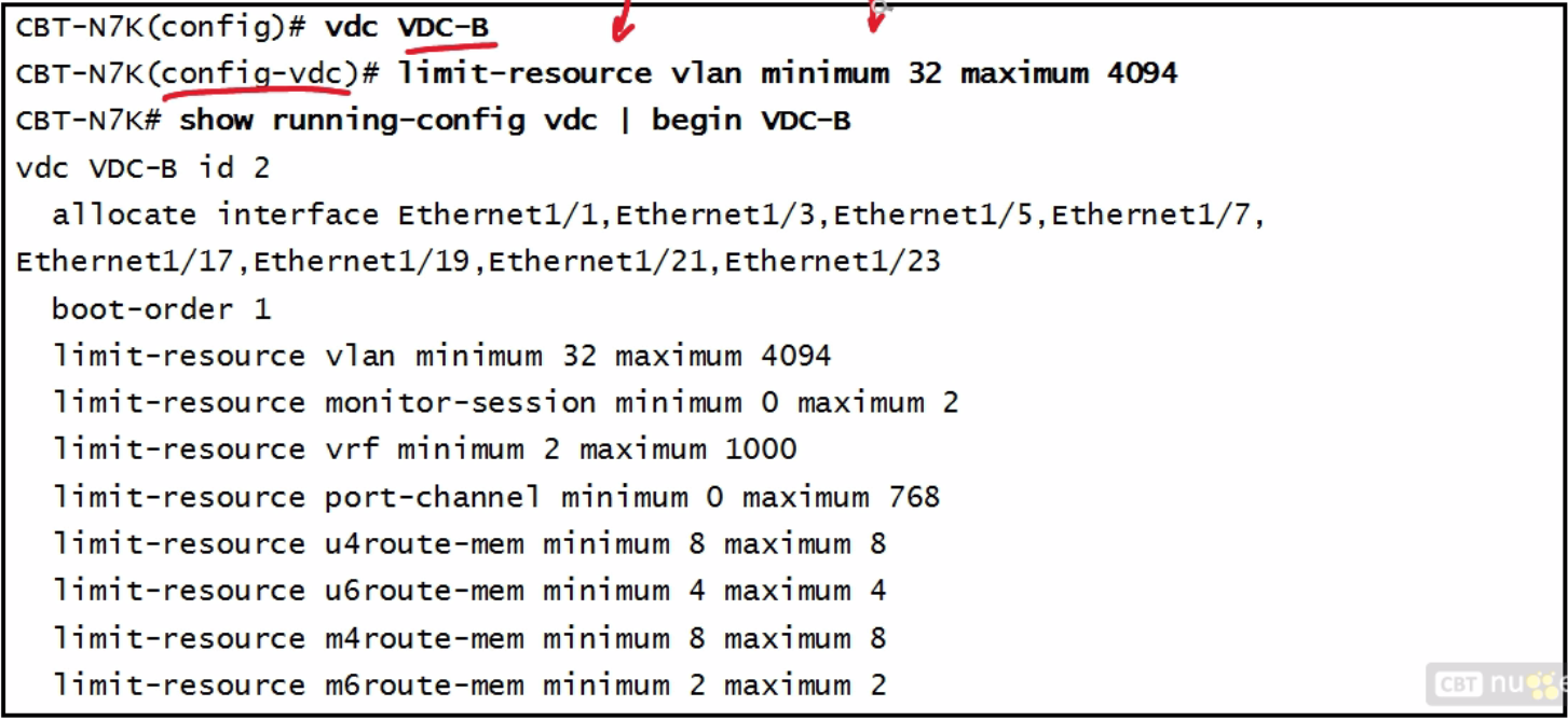 |
| FabricPath | Cisco's implementation of TRILL |
| What does FabricPath work on | 1. 5500s 2. 7K F1 or F2 - needs enhanced Layer 2 License |
| SPINE in FabricPath | do not connect to STP |
| Edge | Connect to STP |
| 2 types of VLANs | 1. FabricPath VLANs 2. Classic VLANs |
| 3 Outer Destination Field | 1.Switch ID - is in outer DA is 12 bits each switch 2. Subswitch ID - identifies port channels and hosts 8 bits 3.Port ID - 16 bits utilizes destination or source interface |
| 2 Fabric Path Tag | 1. FTag - forwarding tag 10 bits multicast or topology 2. TTL - decrements TTL by 1 |
| 7 (2 optional) Steps to Fabric Path Config | 1)Install feature set 2)Enable the feature set (in VDC if are in 7K) 3)Enhanced layer 2 License 4)Fabric Path Switch ID 5)STP parameters 6) Interfaces 7)FP VLANS 8) Virtual Switch ID - vPC+ (optional) 9. Tune load balancing (optional) |
| Actual Fabric Path Configuration Commands | 1. install feature-set fabricpath 2. feature-set fabricpath 3. fabricpath switch-id 11 4. spanning-tree vlan 6-20 priority 8192 5. interface e2/11 - 15 6. (config-if)# switchport mode fabricpath 7. (config-if)# interface port-channel 1 8. (config-if)# switchport mode fabricpath 9. vlan 10-30 10. (config-vlan)# mode fabricpath 11. vpc domain 1 (config-vpc-domain)# fabricpath switch-id 1000 12. fabricpath load-balance unicast layer3 13. fabricpath load-balance multicast include-vlan |
| 7 Verification Commands FabricPath | 1)Show feature-set 2) Show feature-set services fabricpath 3)Show fabricpath switch id 4)Show fabricpath topology vlan active 5)Show mac address-table dynamic vlan 10 6)Show fabricpath isis route 6) Show fabricpath route |
| 6 Layer 3 OSPF config commands | 1)Feature ospf 2)(config-if)# no switchport 3)(config-if)# ip address 10.10.10.1/24 4)(config-if)# ip router ospf 1 area 0 5)(config)# router ospf 1 6)(config-router)# router-id 1.1.1.1 |
| 3 OSPF Verification Commands | 1) Show ip ospf 2)Show ip ospf neigh 3) Show ip ospf int |
| 3 Stateful Restart (NSR) definition and when it works | non-stop routing 1.start from previous run-state with no neighbor event 2.First recovery 3.ISSU or system switchover |
| 3 Graceful Restart and NSF definition and when it works | non-stop forwarding 1. second recovery attempt 2. restart routing protocol 3. active sup removal or reload |
| NSF what it does | 1) Remain in data path 2) Sends out link-local opaque LSA (type 9) 3)Grace period - duration of time when neighbor hangs onto LSA |
| NSF configuration | IS A DEFAULT - (config-router) 1)Grace-period - how long should hold 2)Helper-disable - do not listen to LSA 3)Planned-only - only works if planned |
| VRRP config | 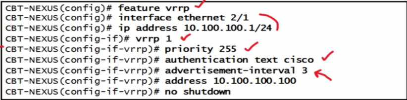 |
| HSRP config | 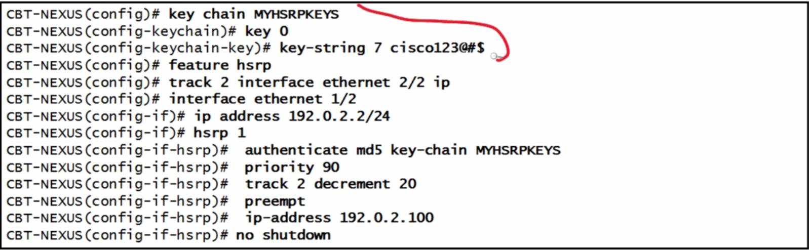 |
| GLBP config | 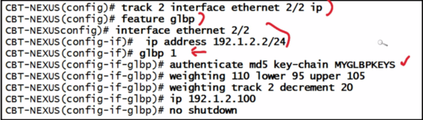 |
| 3 Types of GLBP configurations | 1.Round-robin 2.Weighting 3.Host-dependent - particular host gets a particular forwarder |
| 3 FHRP configs in a graph | 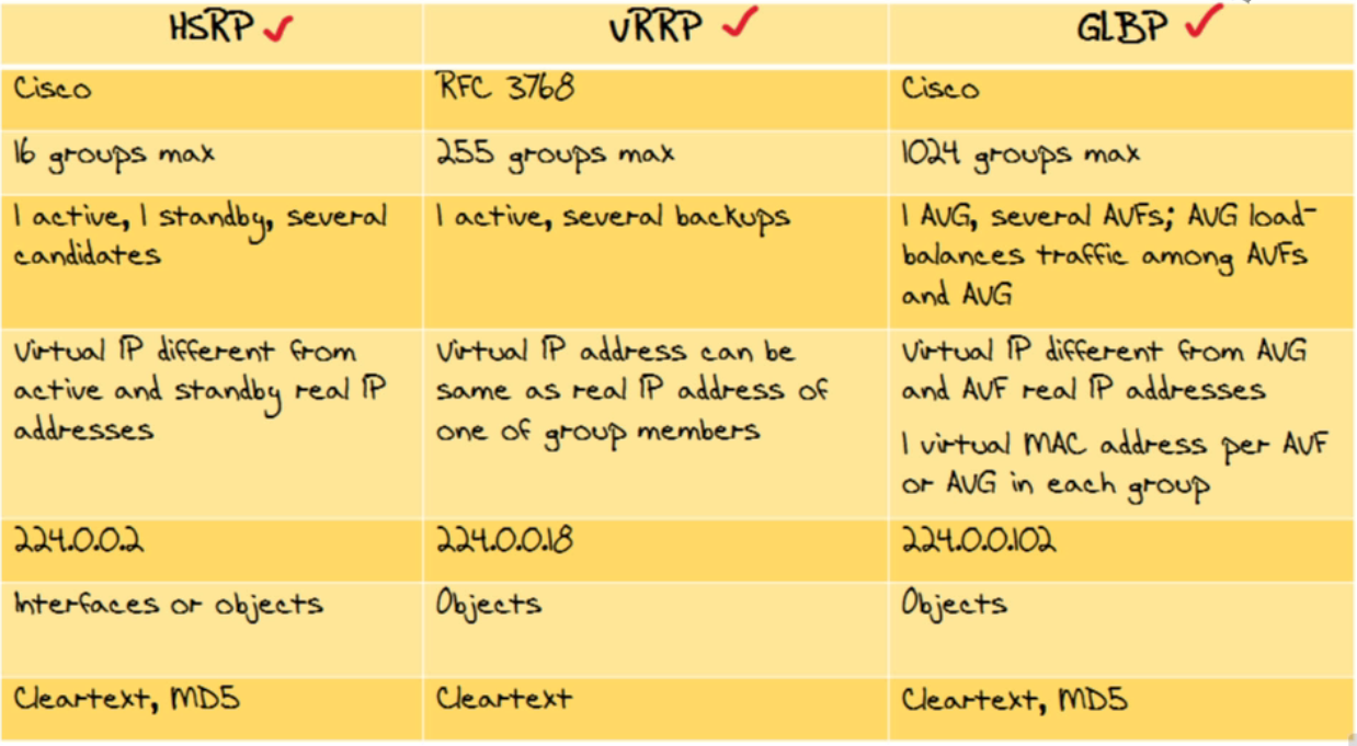 |
| PBR (policy based routing) functions | 1)Dictates forwarding 2)IS FOR TRAFFIC GOING THRU ROUTING 3)LOCAL POLICY - for traffic from routing |
| How does PBR dictate forwarding | 1.Match follow a specific path 2.Deny - follow the normal routing path 3.No match - follow normal path |
| 5 PBR Criteria | 1)Interfaces 2)Ip addresses 3)Default interfaces 4)Default next-hop addresses 5)Load balance across 16 hops |
| 5 PBR Caveats | 1)Enterprise services license - on same VDC 2)One match one set 3)Same route map per VRF 4)No tunnel interfaces 5)No inbound FEX |
| PBR configuration | 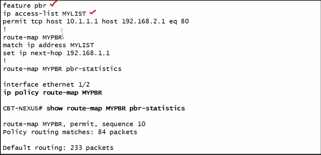 |
| IGMPv2 | any source |
| IGMPv3 | SSM |
| MLDv1 (ipv6) | anycast |
| MLDv2 (ipv6) | SSM-llike behaviour |
| 3 types of PIM | 1)Sparse Mode - routes multicast traffic - efficient builds 2)BiDir 3)SSM |
| INTERDOMAIN PROTOCOLS (multicast) | MSDP and MBGP (multi-protocol BGP) |
| IGMP snooping | on by default - can turn off by vlan - takes place in the domains does not flood just sends it to the ones who want it |
| IGMP configuration if there is no layer 3 address | 1. vlan configuration 10 2. (config-vlan-config)#ip igmp snooping querier 192.168.37.1 |
| Licenses needed by device | 1. 5k Layer 3 base 2. 7k - enterprise services license on F and M must be on same VDC 3. vPC only support Any Source Multicast (ASM) PIM |
| 3 PIM configuration and 2 verificiation | 1)FEATURE PIM 2)Int e2/1 3)(config-if)# Ip pim sparse mode 4)Show ip igmp interface brief 5)Show ip pim interface brief |
| OTV | Overlay Transport Virtualization L2- L3 - L2 |
| OTV Edge Device | edge of DC and OTV setup 1. multi-homing 2. must discover their neighbors in 2 ways a). multicast b). adjacency server register self with it and it will communicate with all the rest |
| OTV Internal | Overlay interfaCE (NO otv setup) |
| OTV Join Interface | sends to OTV cloud |
| 2 things OTV AED does | 1.Forwards L2 unicast, broadcast and multicast over site and the overlay 2.Advertises MAC reachability from other remote devices |
| 3 OTV Beginning of Configuration | 1. Int e1/25 2.(config-if)#ip address 10.1.1.1/24 3.(config-if)# ip igmp version 3 (needed for SSM) |
| 3 OTV Join interface Configuration | 1.(config)# feature OTV 1. 7K - transport services license 2.(config)# otv site-vlan 200 (internal only - do not extend over OTV - critical) 3.(config)# otv site-identifier 201 |
| 6 OTV OVERLAY INTERFACES | 1. Interface overlay 1 2.(config-if-overlay)# otv control-group 239.1.1.1 - multicast group for control traffic 3. (config-if-overlay)# otv data-group 239.1.1.0/28 - multicast subnet moving data 4. (config-if-overlay)# otv extend-vlan 100-199 5.(config-if-overlay)# otv join-interface e1/25 6.(config-if-overlay)# no shut |
| LISP | a) RLOC - is the location address b) EID - endpoint identifier c) LISP Header d) Ingress Tunnel Router e) Egress Tunnel Router f) Map Resolver g) Map Server |
| 5 CONFIGURE DHCP SNOOPING | 1.Feature dhcp-snooping 2.Ip dhcp snooping 3.Ip dhcp snooping vlan 100 4. Interface ethernet 2/1 5. Ip dhcp trust - only put on legit ports |
| 5 Configuration of DYNAMIC ARP INSPECTION | stop gratutious arp - arp spoofing 1. Ip arp inspection vlan 100 2. Ip arp inspection log-buffer entries 1024 - stops ddos 3. Arp access-list MYARP_ACL 4. Permit ip host 10.1.1.16 mac gost BEEF.203B.bA85 5. Ip arp inspection filter MYARP_ACL vlan 100 |
| 2 Ip source guard | 1. Int e2/10 2. Ip verify source dhcp-snooping-vlan |
| Unicast RPF function | unicast reverse path forwarding Checks the route in the source ip to make certain it has a route back to the source |
| Unicast RPF loose configuration | (config-if)# Ip verify unicast source reachable-via any |
| Unicast RPF strict configuration | (config-if)# 1. Ip verify unicast source reachable-via rx |
| Traffic Storm Control | 1. Interface port-channel 10 2. Storm-control broadcast level 30 3. Storm-control multicast level 20 4. Storm-control unicast level 40 |
| 3 levels of port security | 1. Protect - disallows bad mac and not alerts (cisco says not to use) 2. Restrict - disallow bad mac and alerts you 3. Shutdown - (default) - shutdown port |
| COPP 3 parts | use MQC to lock down certain aspects 1. class-map 2. policy-map 3. service-policy |
| COPP policy config | 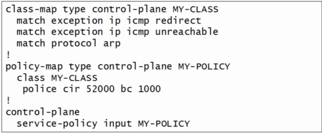 |
| 4 Trustsec | 1. Scalable Security access via SGTs 2. 2 byte tag supports 64k groups 3. Security Group ACLs (SGACL) 4. Integrates with 802.1x |
| 5 Layers to Fibre Channel | 1) SCSI 2) Fibre Channel Protocol 3) Fibre Channel 4) FCOE 5)Ethernet |
| 5 FC Ports - ports have designators based on Function | 1) N (node) Port - Host 2) F (Fabric) Port - Host Port Plugs into a switch 3)E (Expansion) Port - Switch plugs into another port 4) FL (Fabric Loop) Port 5)NL (Node Loop) Port |
| 4 FC Framing (initiator) | 1.Word - communicates initiator to target - 4 bytes 2.Frames series of words 3.Sequence is series of frames 4. Exchange series of frames |
| FC Framing (Target) | is the second part to the equation |
| RSCN | registered state change notification - any changes communicated here |
| FLOGI | n port logs into attached f port a) PLOGI (port login) - NPort must login to other NPort b) PRLI - process login - upper layer login |
| FLOW CONTROL | Tx - Rx Transmit counts the number of free ports or buffers on Receive Port Only transmits when they are certain it will be accepted |
| 3 FC Addressing | 1) nWWN - node world wide names - devices 2) pWWN - port world wide names - ports on devices c) Fibre Channel ID - 24 bit i. Domain ID - switch - 8 bit 1. Only max of 239 - 01-EF <-> F0-FF 2. Cisco support 80 ii. Area ID - groups of Fabric - Fabric Loops - 8 bit iii. Port ID - devices on port - 8 bit |
| VSANs | virtual storage area network |
| Each VSAN has its own stuff | 1.FLOGI Server 2.Distributed Name Server 3. Distributed Zoning 4. FSPF 5. Management Server |
| VSAN connection | 1. TE port - trunking expansion 1.Pass tagged frames 1 - 4093 a) 0 - 4095 - reserved b) VSAN 1 - default, cannot delete all ports placed there c) 4094 - isolated ports cannot be deleted 2. Can disable certain ones from being passed ii. EISL - enhanced interswitch link iii. VSANs work based on Tagging if it is regular ports strips away TAG |
| IVR | inter VSAN routing 1)Transit VSAN 2)Edge devices IVR enabled switches 3)Connect to edge switches within the VSAN |
| Zone sets | 1.Zone set is activated or deactivated 2.One zone set can be active at a time 3. Zone can be a member of more than one set 4. Zone consists of multiple zone members |
| Zoning Rules | 1.Zones can overlap 2. Zones typically do not cross VSANs boundries 1. Unless in IVR 3. Zones are per-VSAN significant |
| Zoning membership | 1. Soft zoning - software based - FCNS - 2. Hard zoning - hardware based - ACL 3. Zone membership - 9 different ways |
| VSAN and Zone information graph | 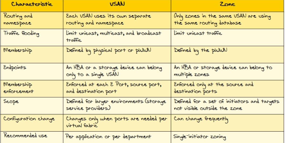 |
| NPIV | allows multiple Fibre Channel IDs to be assigned to single N Ports |
| 3 NPIV traits | 1.Can do zoning 2.Port security 3. Can be applied at VM level 4.DEVICE SUPPORT 1. NPIV Core a) MDS 9500, 9222i, 9124 b) Nexus 5K |
| NPV | blade switch or ToR behaves as an NPIV |
| 2 NPV Traits | 1. NP port off NPV Edge goes to NPIV core 2. DEVICE SUPPORT a) MDS 9124 b) Fabric Interconnects c) Nexus 5K |
| Fibre Channel over Ethernet | does both Fibre Channel and Ethernet |
| 4 FCOE Requirements | 1) Jumbo Frames 2) FC IDs must be mapped to maps 3) Lossless 4) 10gbps |
| 6 FCOE Device Support | a)5k b)55k 3)7k i.5.2(1) ii. Need to use storage vdc (only one per system) no default iii. F1 4)MDS 9k 5) MDS 95k 6)2k |
| 6 FCOE Ports | 1)ENode - end nodes 2)FCF - fibre channel forwarders (aka switches) i. Combo FCOE and Fibre Channel ii.Dual Stack switches 3)Converged network adapters (CNA)s - HBA (host bus adapters in Fibre Channel) 4)VN Ports - virtual fibre channel ports (N Ports in Fibre Channel) 5)VF Ports - virtual fabric ports (F Ports in Fibre Channel) 6)VE Port - connects two FCFs |
| 2 FCOE Protocols | 1)FCOE Protocol - fibre channel info and scsi traffic i.0x8906 1.Data plane 2)FIP (Fabre Channel Initialization Protocol) - discovers fcfs and virtual links etc. i. 0x8914 1.Control plane |
| Direct Attached FCOE | 10 maps to LAN - 20 maps to VSAN 2 - 30 maps to VSAN 3 |
| VPCs with FCOE | 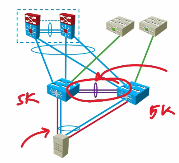 |
| Remote attached FCOE | Passthrough devices do not run FCOE 1.FIP is still there though 2.4Ks can run FIP Snooping and create dyanmic ACLs to prevent spoofing of FC end devices a) FC-BB-5 standards define FIP snooping |
| FCOE NPV | NPV - passthrough proxies - Assigns FCOE vlan but FCF does the heavy lifting |
| FCOE with FEX | 1)Can support NIC teaming and VPC 2) FEX must be single homed 3)Hosts must have Gen 2 adapted FIP capable |
| Multi-hop FCOE | 1) VE port makes multi-hop possible i. Can be port-channel ii. STP disabled 2) 7 hop network diameter 3) 10,000 logins per fabric 4) 8,000 zones 4) 500 zone sets per switch 5) Device support i. 5k ii. 55k iii. MDS 9500k iv. UCS 6200 |
| FCOE Standards | 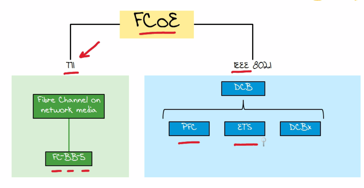 |
| DCB Standards | see picture, 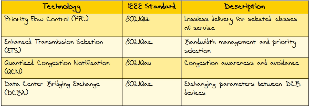 |
| 3. PFC - priority FLOW control | 1)PAUSE based on 802.1p COS - 8 bit 2)No-drop class for FCoE 3)DEFAULT FCOE class is 3 011 (is an 8 bit) 4)Link-level is still an alternative but is disabled in PFC 5)IEEE 802.3x - Link Level Flow control i. Uses an ethernet pause frame ii. Issue is it shuts down the link for the pause frame - ALL TRAFFIC |
| ETS | 802.1Qaz Minimum BW guarantee Can dynamically adjust |
| DCBx | 1)802.1Qaz 2)Negotiation of PFC, ETC etc. 3)Distribute a list of parameters 4)Link up and down signaling 5)Extension of LLDP i.TLV format ii.802.1AB format |
| Cisco Prime DCNM | Data Center Network Management Replace Cisco Fabric Manager Can License for LAN or SAN |
| DCNM Advantages | 1)Health Monitoring 2)VM Features 3)FCO 4)Topology Views 5)FCoE 6)Custom Reports |
| DCNM Modules | 1)Server 2)Client 3)Web-Client 4)DM - device manager 5)Performance Manager 6)Cisco Traffic Manager |
| DCNM Device Support | 1)9500, 9200, 9100 2)Nexus 7k, 5k, 3k 3)UCS Fabric Interconnects 6100, 6200 |
| 2 Editions | 1)Essentials - free 2)Advanced Edition - licensing based on # |
| Cisco Device Manager | can be used to manage an individual switch |
| Cisco Device Manager what it does | 1)VSAN creation 2)SAN port channels 3)Remote Monitoring Alerts 4)SNMP |
| NEXUS 5k FCOE configuration | 1.Correct license 2.Enable FCOE 1.Must reboot after enabled 3.Trunking and flow control 1.Must be in portfast 2.Must permit FCOE VLAN 4.Disable LAN traffic on FCOE 1.When enable sends LLC exchange and brings down all non-FCOE 5.FCOE MAC address prefix 1.Can configure FC-MAP a)Discards all frames not part of current Fabric 6.Fabric Priority 1.Used to determine best switch to connect to 7.Advertisement Interval |
| FCOE config | 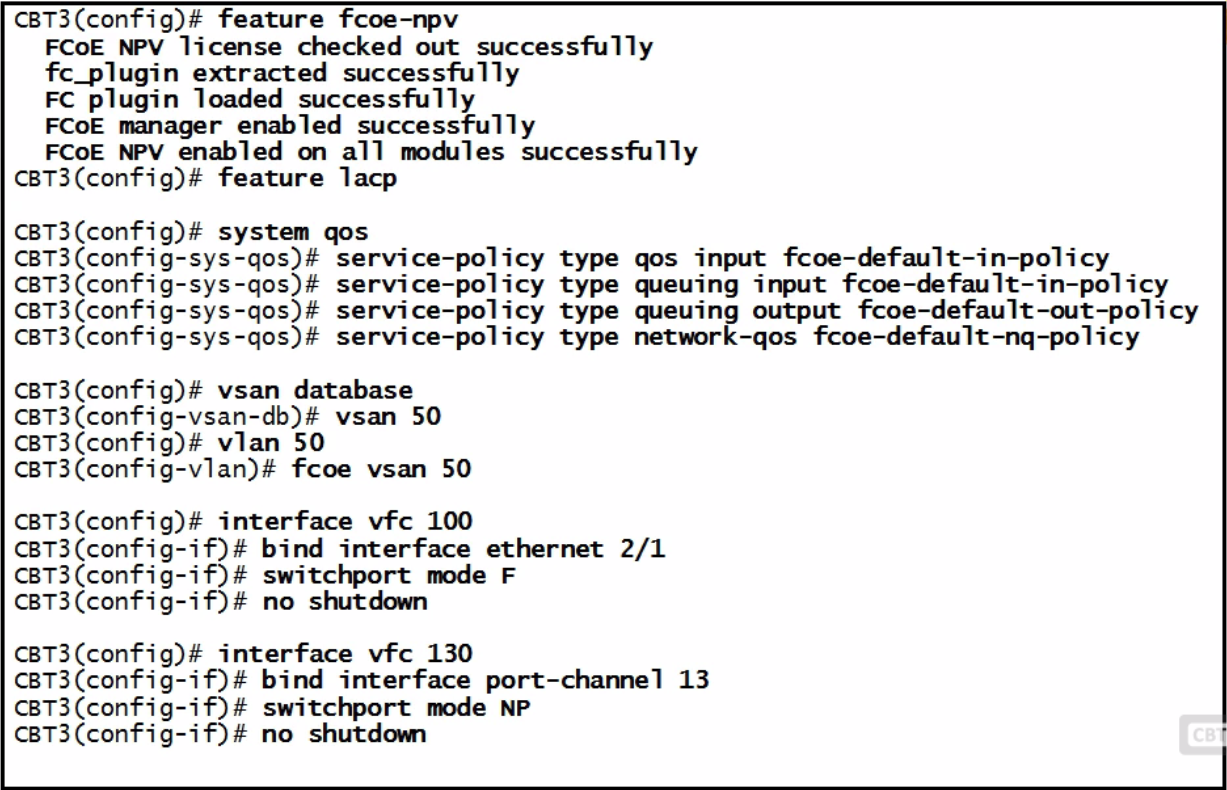 |
| Nexus 7K FCoE | a)Steps done in default VDC i.License each module ii.Install FCoE feature set 1.LLDP required iii.Enable FCoE QoS iv.FCoE trunking v.Storage VDC 1.Configure VDC and allocate interfaces b)Storage VDC i.Enable Features in Storage VDC 1.LLDP ii.Enable Optional FCoE parameters 1.Shared 2.Dedicated |
| FCoE VLANs and Virtual interfaces | 1)Configure a vlan for each SAN 2)Map the VLAN to the SAN 3)Configure a Virtual FC interface 4)Bind the virtual to a physical 5)Associate to the VSAN |
| FCOE Interfaces | 1.Ethernet or Port Channel 2.FIP Snooping 3.Trunks - have to be 4.Portfast - have to be |
| FCoE VLAN Mapped to VSAN | 1.Must be in the Allowed list 2.Not native vlan 3.Restrict to FCoE only 4.Not VLAN 1 5.No private vlans |
| 7K FCOE Guidelines | 1)Gen 2 or newer CNA (converged network adapters) 2)Consistent QoS Policy 3)Storage VDC |
| Storage VDC | 1.Storage only - and FCoE only there 2.FCoE VLAN allocation in allocated range 3.F Series - no rollback 4.Shared interface a.can only be shared with one other VDC b.Can’t do SPAN and some other things |
| FC Interface Configs | see picture |
| FC Speed | i.1, 2, 4, 8 Gbps 1.4 auto by default |
| FC Max Received Buffer Size | i.Max 2112 bytes 1.Range 256-2112 |
| Bbcredit | Range 1-64 |
| Bit error threshold | 15 in 5 minutes default is to disable |
| FC Domain | 1)Principle Switch Selection i.Guarantees unique principle switch across fabric 1.CANNOT BE AN EDGE SWITCH 2)Domain ID distribution i.Each switch gets a unique domain ID 3)FCID allocation i.Each device gets a unique ID 4)Fabric reconfiguration |
| FC Domain Configuration | 1.)fcdomain domain 3 static vsan 2.)fcdomain domain 5 preferred vsan 14 3).fcdomain priority 200 vsan 10 4).fcdomain restart disruptive vsan 10 |
| vsan configuration | 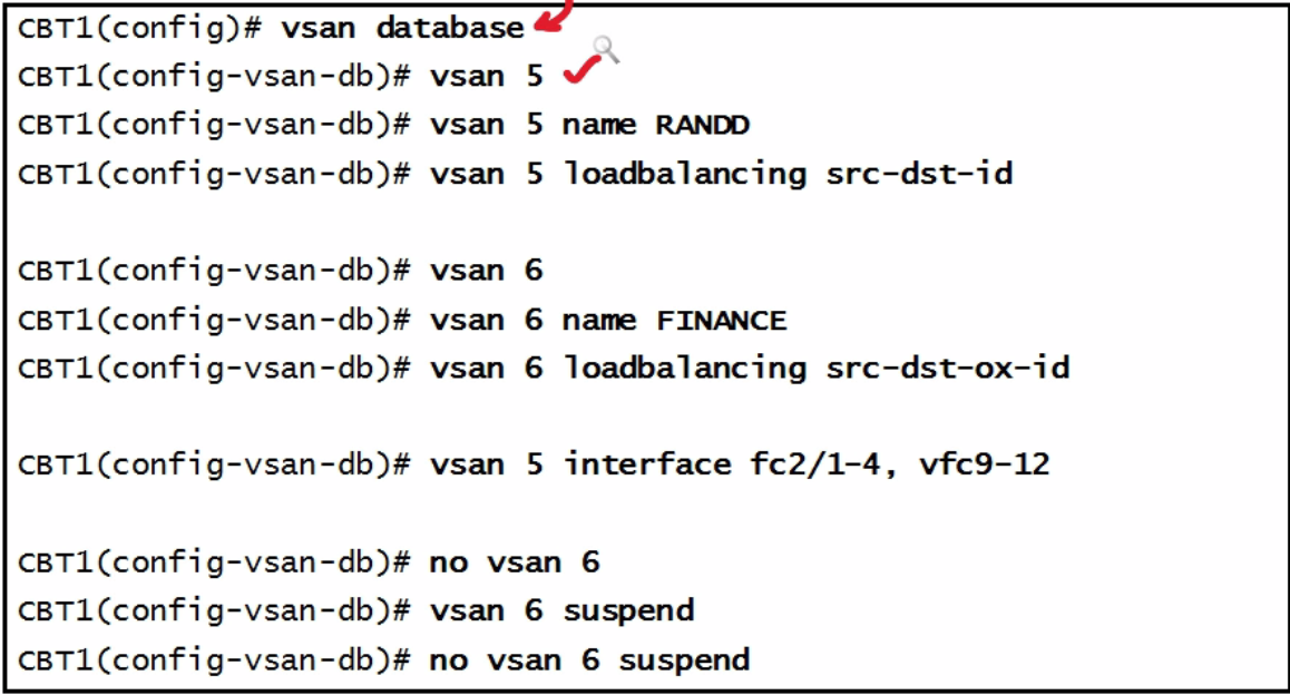 |
| vsan trunk configuration | 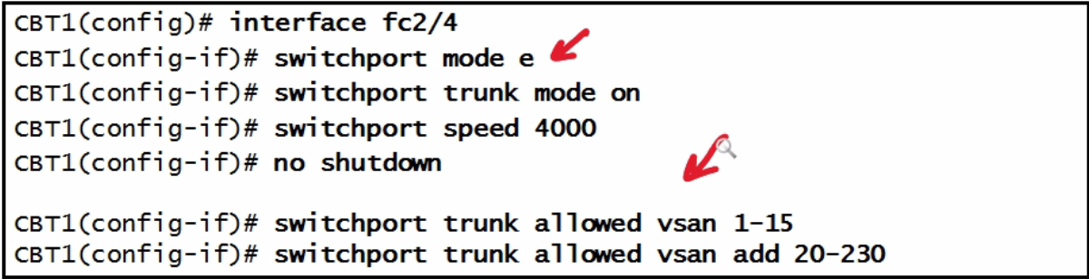 |
| Local account overrides AAA | 1). Network-admin - rw 2).Network-operator - r 3).Vdc-admin - rw 4).Vdc-operator - r |
| Local User Account Management | 1). local user account overrides AAA 2). can configure your own local roles |
| Password Strength Check Traits | 1).8 character long 2).Doesn’t have consecutive characters 3).Does not contain many repeating character 4).No dictionary words 5).No proper name 6).Contains both upper and lower case 7).Contains numbers |
| Encrypting Stored Passwords | 1). switch#Key config-key ascii 2).(config)# Feature password encryption aes 3).Switch# encryption re-encrypt obfuscated i.Can also decrypt |
| Radius Config | 1).Aaa group server radius MYGROUP 2).(config-radius)# server 10.10.1.1 3).(config-radius)# server 10.10.20.2 4).(config-radius)# deadtime 30 5).(config-radius)# use-vrf management |
| Fabric Interconnect | 1).Fabric interconnect connects to UCS chassis via an Input output module or IOM 2).EHV - fabric interconnect runs that so you can eliminate STP 3).Unified Ports - can be Fibre Channel or Ethernet i.Ports must be contiguous for instance 4).NPIV |
| NPIV config | 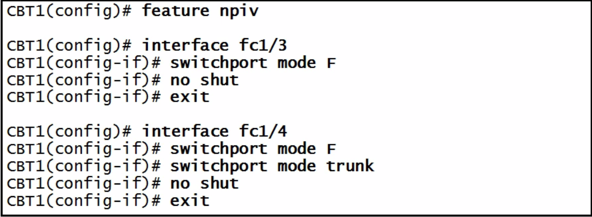 |
| NPV | 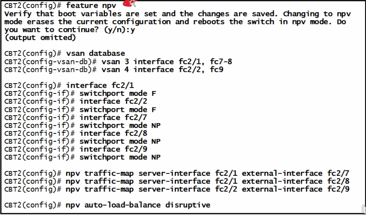 |
| FCOE-NPV CONFIG | see picture |
| CFS definition | cisco fabric services |
| CFS setup | a)In-band - OOB - IPv4 or IPv6/FC b)Physical Scope - not VSANs c)Logical Scope - VSANs d)Uncoordinated replication - no conflict occurs e)Coordinated Replication - careful one main device locks the others |
| CFS application - mode - scope | 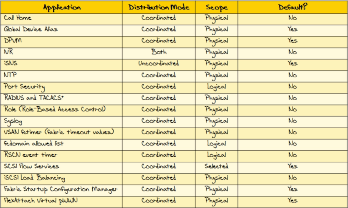 |
| Show cfs application | which ones can take advantage and which scope |
| cfs config | 1).Cfs distribute 2).Ntp distribute 3).Ntp server 172.16.2.10 4).Ntp commit |
| vNIC Template definition | This policy defines how a vNIC on a server connects to the LAN. This policy is also referred to as a vNIC LAN connectivity policy. Cisco UCS Manager does not automatically create a VM-FEX port profile with the correct settings when you create a vNIC template. If you want to create a VM-FEX port profile, you must configure the target of the vNIC template as a VM. You need to include this policy in a service profile for it to take effect. |
| 5 Things needed to create vNIC profile | 1). Named VLAN 2). MAC pool 3). QoS policy 4). LAN pin group 5). Statistics threshold policy |
| 6 vNIC configuration steps | 1 Navigation pane>LAN tab. 2 LAN tab, expand LAN > Policies. 3 Expand node to create the policy. If does not include multitenancy, expand root node. 4 Right-click the vNIC Templates node choose Create vNIC Template. Step 5 In Create vNIC Template dialog box: Dynamic vNIC Connection Policy drop-down list Step 6 Click OK. What to Do Next Include the vNIC template in a service profile. |
| 9 Binding a vNIC to vNIC template | Step 1 In the Navigation pane, click the Servers tab. Step 2 On the Servers tab, expand Servers > Service Profiles. Step 3 Expand the node for the organization that includes the service profile with the vNIC you want to bind. If the system does not include multi-tenancy, expand the root node. Step 4 Expand Service_Profile_Name > vNICs. Step 5 Click the vNIC you want to bind to a template. Step 6 In the Work pane, click the General tab. Step 7 In the Actions area, click Bind to a Template. Step 8 In the Bind to a vNIC Template dialog box, do the following: a) From the vNIC Template drop-down list, choose the template to which you want to bind the vNIC. b) Click OK. Step 9 In the warning dialog box, click Yes to acknowledge that Cisco UCS Manager may need to reboot the server if the binding causes the vNIC to be reconfigured. |
| 8 unbinding a vNIC to vNIC template | Step 1 In the Navigation pane, click the Servers tab. Step 2 On the Servers tab, expand Servers > Service Profiles. Step 3 Expand the node for the organization that includes the service profile with the vNIC you want to unbind. If the system does not include multi-tenancy, expand the root node. Step 4 Expand Service_Profile_Name > vNICs. Step 5 Click the vNIC you want to unbind from a template. Step 6 In the Work pane, click the General tab. Step 7 In the Actions area, click Unbind from a Template. Step 8 If the Cisco UCS Manager GUI displays a confirmation dialog box, click Yes. |
| 5 Deleting a vNIC template procedure | Step 1 In the Navigation pane, click the LAN tab. Step 2 On the LAN tab, expand LAN > Policies > Organization_Name. Step 3 Expand the vNIC Templates node. Step 4 Right-click the policy you want to delete and choose Delete. Step 5 If the Cisco UCS Manager GUI displays a confirmation dialog box, click Yes. |
| 9 Steps to Ethernet Adapter Configuration Policy Fibre Channel | Step 1 In the Navigation pane, click the Servers tab. Step 2 On the Servers tab, expand Servers > Policies. Step 3 Expand the node for the organization where you want to create the policy. If the system does not include multitenancy, expand the root node. Step 4 Right-click Adapter Policies and choose Create Ethernet Adapter Policy. Step 5 Enter a name and description • Local—This policy is available only to service profiles and service profile templates in this Cisco UCS domain. • Pending Global—Control of this policy is being transferred to Cisco UCS Central. Once the transfer is complete, this policy will be available to all Cisco UCS domains registered with Cisco UCS Central. • Global—This policy is managed by Cisco UCS Central. Any changes to this policy must be made through Cisco UCS Central. Owner field Step 6 (Optional) In the Resources area Step 7 (Optional) In the Options area, adjust the following values: Interrupt Timer field Step 8 Click OK. Step 9 If the Cisco UCS Manager GUI displays a confirmation dialog box, click Yes. |
| 9 Steps LAN Connectivity Policy Procedure | Step 1 In the Navigation pane, click the LAN tab. Step 2 On the LAN tab, expand LAN > Policies. Step 3 Expand the node for the organization where you want to create the policy. If the system does not include multitenancy, expand the root node. Step 4 Right-click LAN Connectivity Policies and choose Create LAN Connectivity Policy. Step 5 In the Create LAN Connectivity Policy dialog box, enter a name and description for the policy in the following fields: Name Description The name of the policy. This name can be between 1 and 16 alphanumeric characters. You cannot use spaces or any special characters other than - (hyphen), _ (underscore), : (colon), and . (period), and you cannot change this name after the object has been saved. Name field A description of the policy. We recommend that you include information about where and when the policy should be used. Enter up to 256 characters. You can use any characters or spaces except ` (accent mark), \ (backslash), ^ (carat), " (double quote), = (equal sign),> (greater than), < (less than), or ' (single quote). Description field Step 6 Do one of the following: • To add vNICs to the LAN connectivity policy, continue with Step 7. • To add iSCSI vNICs to the LAN connectivity policy and use iSCSI boot with the server, continue with Step 8. Step 7 To add vNICs, in the vNIC Table area, click + on the table icon bar and complete the following fields in the Create vNIC dialog box:Step 8 If you want to use iSCSI boot with the server, click the down arrows to expand the Add iSCSI vNICs bar and do the following: a) Click + on the table icon bar. b) In the Create iSCSI vNIC dialog box, complete the following fields e) Click OK. Step 9 After you have created all the vNICs or iSCSI vNICs you need for the policy, click OK. What to Do Next Include the policy in a service profile or service profile template. |
| 5 Steps Deleting Ethernet Adapter Policy Procedure | Step 1 In the Navigation pane, click the LAN tab. Step 2 On the LAN tab, expand LAN > Policies > Organization_Name. Step 3 Expand the Adapter Policies node. Step 4 Right-click the Ethernet adapter policy that you want to delete and choose Delete. Step 5 If the Cisco UCS Manager GUI displays a confirmation dialog box, click Yes. |
| 6 Configuring a Default vNIC Behavior Policy Procedure | Step 1 In the Navigation pane, click the LAN tab. Step 2 On the LAN tab, expand LAN > Policies. Step 3 Expand the root node. You can configure only the default vNIC behavior policy in the root organization. You cannot configure the default vNIC behavior policy in a sub-organization. Step 4 Click Default vNIC Behavior. Step 5 On the General Tab, in the Properties area, click one of the following radio buttons in the Action field: • None—Cisco UCS Manager does not create default vNICs for a service profile. All vNICs must be explicitly created. • HW Inherit—If a service profile requires vNICs and none have been explicitly defined, Cisco UCS Manager creates the required vNICs based on the adapter installed in the server associated with the service profile. Step 6 Click Save Changes. |
| Configuring LAN Connectivity Policies LAN and SAN Connectivity Policies | Connectivity policies determine the connections and the network communication resources between the server and the LAN or SAN on the network. These policies use pools to assign MAC addresses, WWNs, and WWPNs to servers and to identify the vNICs and vHBAs that the servers use to communicate with the network. We do not recommend that you use static IDs in connectivity policies, because these policies are included in service profiles and service profile templates and can be used to configure multiple servers. |
| Privileges Required to Create Connectivity Policies | Connectivity policies require the same privileges as other network and storage configurations. For example, you must have at least one of the following privileges to create connectivity policies: • admin—Can create LAN and SAN connectivity policies • ls-server—Can create LAN and SAN connectivity policies • ls-network—Can create LAN connectivity policies • ls-storage—Can create SAN connectivity policies |
| Privileges Required to Add Connectivity Policies to Service Profiles | ls-compute |
| Interactions between Service Profiles and Connectivity Policies | You can configure the LAN and SAN connectivity for a service profile through either of the following methods: • LAN and SAN connectivity policies that are referenced in the service profile • Local vNICs and vHBAs that are created in the service profile • Local vNICs and a SAN connectivity policy • Local vHBAs and a LAN connectivity policy Cisco UCS maintains mutual exclusivity between connectivity policies and local vNIC and vHBA configuration in the service profile. You cannot have a combination of connectivity policies and locally created vNICs or vHBAs. When you include a LAN connectivity policy in a service profile, all existing vNIC configuration is erased, and when you include a SAN connectivity policy, all existing vHBA configuration in that service profile is erased. |
| 8 Creating a vNIC for a LAN Connectivity Policy Procedure | 1. In the Navigation pane, click the LAN tab. 2. On the LAN tab, expand LAN > Policies > Organization_Name. 3. Expand the LAN Connectivity Policies node. 4. Choose the policy to which you want to add a vNIC. 5. In the Work pane, click the General tab. 6. On the icon bar of the vNICs table, click Add. 7. In the Create vNIC dialog box, 8. Click OK. 9. Click Save Changes. |
| 8 Deleting a vNIC from a LAN Connectivity Policy Procedure | 1. In the Navigation pane, click the LAN tab. 2. On the LAN tab, expand LAN > Policies > Organization_Name. 3. Expand the LAN Connectivity Policies node. 4. Select the policy from which you want to delete the vNIC. 5. In the Work pane, click the General tab. 6. In the vNICs table, do the following: a) Click the vNIC you want to delete. b) On the icon bar, click Delete. 7. If the Cisco UCS Manager GUI displays a confirmation dialog box, click Yes. Step 8 Click Save Changes. |
| 11 Creating an iSCSI vNIC for a LAN Connectivity Policy Procedure | 1.Navigation pane>LAN tab. 2.expand LAN > Policies > Organization_Name. 3. Expand LAN Connectivity Policies node. 4.Choose policy to add an iSCSI vNIC. 5. Work pane>General tab. 6. Icon bar of Add iSCSI vNICs table, click Add. 7.Create iSCSI vNIC dialog box,8. In MAC Address Assignment drop-down in the iSCSI MAC Address area, choose 1: • Leave MAC address unassigned,(None used by default). Select this if server associated with service profile contains Cisco UCS M81KR Virtual Interface Card adapter or a Cisco UCS VIC-1240 Virtual Interface Card. If server will be associated with this service profile contains a Cisco UCS NIC M51KR-B adapter, specify a MAC address. Important • A specific MAC address, select 00:25:B5:XX:XX:XX enter the address in the MAC Address field. To verify that this address is available, click the corresponding link. • A MAC address from a pool, select pool name from list. Each pool name is followed by a pair of numbers in parentheses. The first number is the number of available MAC addresses in the pool the second is the total number of MAC addresses in the pool. If this Cisco UCS domain is registered with Cisco UCS Central, there may be two pool categories. Domain Pools are defined locally in the Cisco UCS domain and Global Pools are defined in Cisco UCS Central. 9 (Optional) If you want to create a MAC pool that will be available to all service profiles, Create MAC Pool and complete the fields in Create MAC Pool wizard. Step 10 Click OK. Step 11 Click Save Changes |
| 8 Deleting an iSCSI vNIC from a LAN Connectivity Policy Procedure | 1. In the Navigation pane, click the LAN tab. 2. On the LAN tab, expand LAN > Policies > Organization_Name. 3 Expand the LAN Connectivity Policies node. 4. Chose the policy from which you want to delete the iSCSI vNIC. 5. In the Work pane, click the General tab. 6. In the Add iSCSI vNICs table, do the following: a) Click the iSCSI vNIC that you want to delete. b) On the icon bar, click Delete. 7. If the Cisco UCS Manager GUI displays a confirmation dialog box, click Yes. 8. Click Save Changes. |
| Deleting a LAN Connectivity Policy impact | If you delete a LAN connectivity policy that is included in a service profile, you will delete all vNICs and iSCSI vNICs from that service profile and disrupt LAN data traffic for the server associated with the service profile. |
| 5 Steps to Deleting a LAN connectivity Policy | 1. In the Navigation pane, click the LAN tab. 2. On the LAN tab, expand LAN > Policies > Organization_Name. Step 3. Expand the LAN Connectivity Policies node. 4. Right-click the policy that you want to delete and choose Delete. 5. If the Cisco UCS Manager GUI displays a confirmation dialog box, click Yes. |
| 9 Create vnic Template Fields | 1. enable failover 2. Fabric ID 3. Adapter 4. VM 5. Target 6. Initial Template 7. Updating Template 8. Template Type 9. name description |
| 9 vNic Name Description Field Information | 1. name VLAN 2. Native VLAN 3. MTU 4. MAC Pool 5. QoS Policy 6. Network Control Policy 7. PIN Group 8. Stats Threshold Policy 9. Dynamic vNIC connection policy |
| 5 Configuring Network Control Policies - Network Control Policy | 1. Whether the Cisco Discovery Protocol (CDP) is enabled or disabled 2. How the virtual interface ( VIF) behaves if no uplink port is available in end-host mode 3. The action that Cisco UCS Manager takes on the remote Ethernet interface, vEthernet interface , or vFibre Channel interface when the associated border port fails. 4. Whether the server can use different MAC addresses when sending packets to the fabric interconnect 5. Whether MAC registration occurs on a per-VNIC basis or for all VLANs |
| Action on Uplink Fail | by default is link down can do warning although no advised in NIC Teaming because it may not detect a link failure |
| MAC Registration Mode | MAC addresses are installed only on the native VLAN by default, which maximizes the VLAN port count in most implementations. If a trunking driver is being run on the host and the interface is in promiscuous mode, we recommend that you set the Mac Registration Mode to All VLANs. |
| 7 Network Control Policy Configuration | 1. In the Navigation pane, click the LAN tab. 2 On the LAN tab, expand LAN > Policies. 3 Expand the node for the organization where you want to create the policy. If the system does not include multitenancy, expand the root node. 4 Right-click the Network Control Policies node and select Create Network Control Policy. 5 In the Create Network Control Policy 1. Name field This option determines whether Cisco Discovery Protocol (CDP) is enabled on servers associated with a service profile that includes this policy. • Disabled • Enabled 2. MAC addresses are added only to the native VLAN associated with the interface or added to all VLANs associated with the interface. This can be one of the following: • Only Native Vlan—MAC addresses are only added to the native VLAN. This option is the default, and it maximizes the port+VLAN count. • All Host Vlans—MAC addresses are added to all VLANs with which they are associated. Select this option if your VLANs are configured to use trunking but are not running in Promiscuous mode. 3. MAC Register Mode field This option determines how the VIF behaves if no uplink port is available when the fabric interconnect is in end-host mode. This can be one of the following: • Link Down— Changes the operational state of a vNIC to down when uplink connectivity is lost on the fabric interconnect, and enables fabric failover for vNICs. Warning only in specific instances 6. MAC Security (allow or deny) 7. ok |
| 5 Deleting a Network Control Policy | 1 In the Navigation pane, click the LAN tab. Step 2 On the LAN tab, expand LAN > Policies > Organization_Name. Step 3 Expand the Network Control Policies node. Step 4 Right-click the policy you want to delete and select Delete. Step 5 If the Cisco UCS Manager GUI displays a confirmation dialog box, click Yes. |
| 6 Creating Multicast Policy | 1 In the Navigation pane, click the LAN tab. Step 2 On the LAN tab, expand LAN > Policies. Step 3 Expand the root node. Step 4 Right-click the Multicast Policies node and select Create Multicast Policy. Step 5 In the Create Multicast Policy dialog box, complete the following fields: 1. Name 2. Whether IGMP snooping examines IGMP protocol messages within a VLAN to discover which interfaces are connected to hosts or other devices interested in receiving multicast traffic. This can be one of the following: • Enabled—IGMP snooping is used for VLANs associated with this policy. • Disabled—IGMP snooping is not used for associated VLANs. 3. IGMP Snooping Querier State field IGMP Snooping Querier IPv4 The IPv4 address for the IGMP snooping querier interface. Address field Step 6 Click OK. |
| 5 Deleting a Multicast Policy | Step 1 In the Navigation pane, click the LAN tab. Step 2 On the LAN tab, expand LAN > Policies. Step 3 Expand the root node. Step 4 Right-click the Multicast Policies node and select Delete Multicast Policy. Step 5 If the Cisco UCS Manager GUI displays a confirmation dialog box, click Yes. |
| VM-FEX Components Server | 1. C Series performed by the CIMC - Cisco Integrated Management Controller 2. Hypervisor and Virtualization services configured by VMWare vSPHere client |
| VM-FEX Components VIC | 1. Virtual interface card UCS P81E Virtual Interface Card (VIC), a dual-port 10 Gigabit Ethernet PCIe adapter that supports static or dynamic virtualized interfaces, including up to 128 virtual network interface cards (vNICs). The configuration of the VIC and its vNICs is performed using the CIMC interface on the Cisco UCS C-Series servers. |
| VM-FEX Components FEX | The physical ports of the server can be connected directly to the switch or to a fabric extender (FEX) connected to the switch. VM-FEX is supported by the Cisco Nexus Fabric Extender. VM-FEX and AFEX require that the FEX is connected with a fabric PO and not individual links. |
| VM-Fex Components Switch | VM-FEX is supported by the Cisco Nexus device. Although a single switch chassis can be connected with VM-FEX, a typical application uses a pair of switches deployed as a virtual port channel (vPC) domain.On the switch, a vEthernet interface represents the vNIC. All operations performed by the network administrator are performed on the vEthernet interface. |
| Virtual Ethernet Interface (vm-fex) | A virtual Ethernet interface (vEthernet or vEth) represents the switch port that is connected to the vNIC of a virtual machine. Unlike a traditional switch interface, a vEth interface's name does not indicate the module with which the port is associated. Where a traditional physical switch port is specified as GigX/Y, where X is the module number and Y is the port number on the module, a vEth interface is specified as vEthY. This notation allows the interface to keep the same name when the VM migrates to another physical server. |
| dynamic interface (vm-fex) | A dynamic interface is a vEthernet interface that is configured automatically as a result of adapter and switch communications. The provisioning model of a dynamic interface consists of the configuration on the switch of a vEthernet port profile, which is propagated to the network adapter as a port group, followed by the association of the port group with the vNIC. The port profile is created in the switch by the network administrator, while the association with the vNIC is performed on the adapter by the server administrator. A static interface is configured manually on the switch and the adapter. A static virtual adapter can be a vNIC or a virtual host adapter bus (vHBA). A static interface can be a vEthernet or a virtual Fibre Channel (vFC) interface bound to a static vEthernet interface. In one method of creating a static vEthernet, the network administrator assigns a channel number (equivalent to a VN-Tag or prestandard IEEE 802.1BR tag number) to the vEthernet. The server administrator must be sure to define a vNIC on the adapter with the same channel number |
| floating vEthernet interface | In another method, the network administrator can create a static floating vEthernet by configuring the vEthernet with a virtual switching instance (VSI) MAC address and DVPort ID.In a hypervisor environment, each vNIC on the network adapter is associated with one virtual machine (VM). VMs can migrate from one physical server to another. A virtual interface that migrates with a VM and virtual network link is called a floating vEthernet interface. |
| fixed vEthernet interface | A fixed vEthernet interface is a virtual interface that does not support migration across physical interfaces. For fixed vEthernet (static or dynamic), an administrator can change configurations at any time. The binding of the vEthernet interface number to a channel number is persistent unless the administrator changes it. |
| configuring vm-fex 11 steps | 1. switch# configure terminal 2. install feature-set virtualization 3. feature-set virtualization 4. feature fex 5. feature vmfex 6. feature vpc 7. (Optional) vethernet auto-create 8. (Optional) feature fcoe 9. (Optional) end 10. (Optional) copy running-config startup-config 11. (Optional) reload |
| 23 steps to manually configuring vNICs | 1 switch# configure t. 2 int eth slot/port.3 shut. Shutting down the interface before enabling VN-Tag mode prevents the dynamic creation of a fixed veth interface. 4 switchport mode vntag Enables port extender support on the interface. 5 int eth slot/port interface configuration mode for the second eth port.6 shut 7 switchport mode vntag Enables port extender support on the interface. Enters configuration mode for the first virtual interface for the first eth port.8 interface veth interface-number Binds the virtual interface to the physical interface and the specified port channel.9 bind interface eth slot/port channel channel-number The port channel numbers of the virtual interfaces must match those configured on the vNICs. 10 no shut Enters configuration mode for the second virtual interface for the first eth port.11 interface veth interface-number Binds the virtual interface to the physical interface and the specified port channel.12 bind interface eth slot/port channel channel-number 13 no shut Enters configuration mode for the first virtual interface for the second eth port. 14 interface veth interface-number Binds the virtual interface to the physical interface and the specified port channel. 15 bind interface eth slot/port channel channel-number 16 no shut Enters configuration mode for the second virtual interface for the second eth port. 17 interface veth interface-number Binds the virtual interface to the physical interface and the specified port channel. 18 bind interface eth slot/port channel channel-number 19 no shut Enables local traffic on the interface. 20 interface eth slot/port Enters configuration mode for the first eth port. 21 no shut 22 interface eth slot/port Enters configuration mode for the second eth port. 23 no shut . With redundant switches, repeat this procedure with identical settings on the secondary switch. |
| Configuring a Port Profile for the Dynamic Interfaces | You can configure a port profile for dynamic virtual interfaces. This port profile is exported to the VMware vCenter distributed virtual switch (DVS) as a port-group. With redundant switches, you can perform the following procedure with identical settings on both the primary and secondary switches. Before You Begin • Dynamic vNICs must be configured on the VIC adapter installed in the host server. • The VLAN specified in the port profile must be created. |
| 7 configuration steps to port profile for the dynamic interfaces | Step 1 Enters configuration mode for the specified port profile, creating it if necessary. Step 2 port-profile type vethernet profilename (Optional) Configures the interface to be in access mode. Step 3 switchport mode access (Optional) Specifies the VLAN when the interface is in access mode. Step 4 switchport access vlan vlan-id Specifies the vCenter DVS to which the port profile is exported as a port-group.With the keyword all, the port profile is exported to all DVSs in the vCenter. Step 5 dvs-name {all | name} (Optional) Specifies dynamic port binding. The port is connected when the VM is powered on and disconnected when the VM is powered off. Max-port limits are enforced. The default is static port binding. Step 6 port-binding dynamic Step 7 state enabled Enables the port profile. |
| Configuring an SVS Connection to the vCenter Server | You can configure a secure connection from the switch to the vCenter Server. With redundant switches, perform this procedure on both the primary and the secondary switches. In normal operation, only the primary switch connects to the vCenter, with the secondary switch connecting only upon a failure of the primary. |
| 8 Configuration Steps for SVS | 1. switch# configure terminal 2. svs connection svs-name 3. protocol vmware-vim 4. vmware dvs datacenter-name dc-name 5. dvs-name dvs-name 6. Choose one: • remote ip address ipv4-addr [port port-num] [vrf {vrf-name | default | management}] • remote hostname host-name [port port-num] [vrf {vrf-name | default | management}] 7. install certificate {bootflash:[//server/] | default} 8. extension-key: extn-ID DETAILED STEPS Command or Action Purpose Step 1 switch# configure terminal Enters global configuration mode. Enables and enters configuration mode for an SVS connection from the switch to the vCenter Server. Step 2 svs connection svs-name Enables the VMware Infrastructure Software Development Kit (VI SDK), which allows clients to communicate with the vCenter. Step 3 protocol vmware-vim Creates a VMware distributed virtual switch (DVS) in the specified datacenter. Step 4 vmware dvs datacenter-name dc-name Step 5 dvs-name dvs-name Configures a name for the DVS in the vCenter Server. Specifies the hostname or IP address for the vCenter Server. Optionally, specifies the port number and VRF. Step 6 Choose one:• remote ip address ipv4-addr [port port-num] [vrf {vrf-name | default | management}] • remote hostname host-name [port port-num] [vrf {vrf-name | default | management}] Command or Action Purpose install certificate {bootflash:[//server/] | Installs a certificate that is used to connect to the vCenter Server. default} Step 7 The server argument specifies the boot flash memory location to install the certificate. The argument value can be module-1, sup-1, sup-active, or sup-local. Configures the extension key to be used to connect to the vCenter Server. Step 8 extension-key: extn-ID With redundant switches, perform this step only on the primary switch. The key is automatically synchronized with the secondary switch. |
| Activating SVS | What to Do Next Activate the connection on the primary switch only. Activating an SVS Connection to the vCenter Server You can activate a connection from the switch to the vCenter Server. Before You Begin • The vCenter Server must be running and reachable. • You must have already registered an extension with the vCenter Server. • The SVS connection must be configured on the switch. Step 1 switch# configure terminal Enters global configuration mode. EnablesandentersconfigurationmodeforanSVSconnectionfromtheswitch to the vCenter Server. Step 2 svs connection svs-name Step 3 [no] connect Initiates a connection with the vCenter Server. With redundant switches, perform this step on both the primary and secondary switches. Only the primary will connect. |
| Verifying the VM-FEX Configuration Verifying the Status of the Virtual Interfaces | show interface vethernet interface-number [detail] Displays information about all floating virtual interfaces. show interface virtual status vm-fex Display summary information about virtual Ethernet interfaces. show interface virtual summary vm-fex Displays information about virtual interfaces on a bound Ethernet interface. show interface virtual status bound interface ethernet port/slot Displays summary information about virtual interfaces on a bound Ethernet interface. show interface virtual summary bound interface ethernet port/slot This example shows how to display status and configuration information about a static interface |
| Verifying the Connection to the vCenter Server | switch-1# configure terminal switch-1(config)# show svs connections |
| Core layer | the high-speed packet switching backplane for all flows going in and out of the data center |
| Aggregation layer | providing important functions such as the integration of network-hosted services: load balancing, intrusion detection, firewalls, SSL offload, network analysis, and more |
| Access Layer | where the servers physically attach to the network and where the network policies (access control lists [ACLs], quality of service [QoS], VLANs, etc.) are enforced The access-layer network infrastructure can be implemented with either large, modular switches, typically located at the end of each row, providing connectivity for each of the servers located within that row (the end-of-row model,) or smaller, fixed configuration top-of-rack switches that provide connectivity to one or a few adjacent racks and have uplinks to the aggregation-layer devices (the top-of-rack model.) Bladed server architectures modify the access layer by allowing an optional embedded blade switch to be located within the blade enclosure. Blade switches, which are functionally similar to access-layer switches, are topologically located at the access layer; however, they are often deployed as an additional layer of the network between access-layer switches and computing nodes (blades), thus introducing a fourth layer in the network design. |
| Figure 1. Comparison of Access Layer Connectivity Options in (1) Nonvirtualized Rack-Optimized Server, (2) Virtualized Rack-Optimized Server, (3) Nonvirtualized Blade Server, and (4) Virtualized Blade Server | 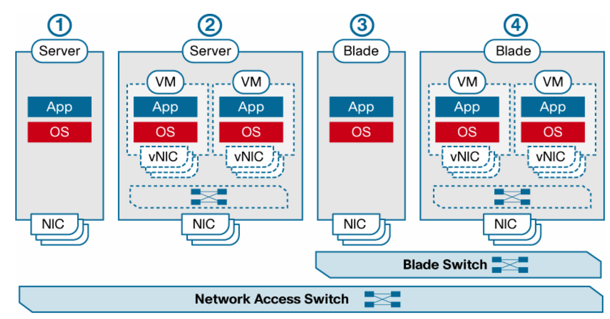 |
| Cisco VN-Link | the DVS framework to deliver a portfolio of networking solutions that can operate directly within the distributed hypervisor layer These features are collectively referred to as Cisco Virtual Network Link (VN-Link). The term literally indicates the creation of a logical link between a vNIC on a virtual machine and a Cisco switch enabled for VN-Link. This mapping is the logical equivalent of using a cable to connect a NIC with a network port of an access-layer switch. |
| virtual Ethernet (vEth) interfaces | . A switch enabled for VN-Link can implement several vEth interfaces per physical port, and it creates a mapping between each vEth interface and the corresponding vNIC on the virtual machine. A very important benefit of vEth interfaces is that they can follow vNICs when virtual machines move from one physical server to another. The movement is performed while maintaining the port configuration and state, including NetFlow, port statistics, and any Switched Port Analyzer (SPAN) session. By virtualizing the network access port with vEth interfaces, VN-Link effectively enables transparent mobility of virtual machines across different physical servers and different physical access-layer switches. |
| port profiles | Port profiles are a collection of interface configuration commands that can be dynamically applied at either physical or virtual interfaces. Any changes to a given port profile are propagated immediately to all ports that have been associated with it. A port profile can define a quite sophisticated collection of attributes such as VLAN, private VLAN (PVLAN), ACL, port security, NetFlow collection, rate limiting, QoS marking, and even remote-port mirroring (through Encapsulated Remote SPAN [ERSPAN]) for advanced, per–virtual machine troubleshooting. |
| port profile example | (config)# port-profile webservers (config-port-prof)# switchport access vlan 10 (config-port-prof)# ip access-group 500 in (config-port-prof)# inherit port-profile server The port profile can then be assigned to a given vEth interface as follows: (config)# interface veth1 (config-if)# inherit port-profile webservers |
| Relationship Between Virtual and Physical Network Constructs in a VN-Link Enabled Switch (Cisco Nexus™ 1000V Series Switches) | 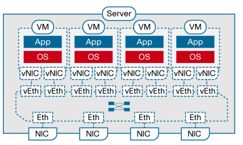 |
| Virtual Ethernet module (VEM)–data plane | This lightweight software component runs inside the hypervisor. It enables advanced networking and security features, performs switching between directly attached virtual machines, provides uplink capabilities to the rest of the network, and effectively replaces the vSwitch. Each hypervisor is embedded with one VEM. |
| Virtual supervisor module (VSM)–control plane | This standalone, external, physical or virtual appliance is responsible for the configuration, management, monitoring, and diagnostics of the overall Cisco Nexus 1000V Series system (that is, the combination of the VSM itself and all the VEMs it controls) as well as the integration with VMware vCenter. A single VSM can manage up to 64 VEMs. VSMs can be deployed in an active-standby model, helping ensure high availability. |
| Cisco Nexus 1000V Series Distributed Switching Architecture | 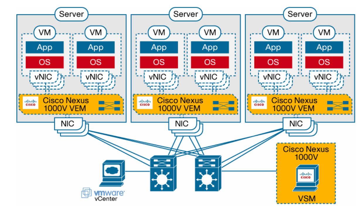 |
| Deploying VN-Link with Network Interface Virtualization | NIV completely removes any switching function from the hypervisor and locates it in a hardware network switch physically independent of the server. NIV still requires a component on the host, called the interface virtualizer, that can be implemented either in software within the hypervisor or in hardware within an interface virtualizer–capable adapter. The purpose of the interface virtualizer is twofold: ● For traffic going from the server to the network, the interface virtualizer identifies the source vNIC and explicitly tags each of the packets generated by that vNIC with a unique tag, also known as a virtual network tag (VNTag). ● For traffic received from the network, the interface virtualizer removes the VNTag and directs the packet to the specified vNIC. |
| virtual interface switch (VIS) | indicate its capability not only to switch between physical ports, but also between virtual interfaces (VIFs) corresponding to vNICs that are remote from the switch. Said in a different way, each vNIC in a virtual machine will correspond to a VIF in the VIS, and any switching or policy enforcement function will be performed within the VIS and not in the hypervisor. The VIS can be any kind of access-layer switch in the network (a blade, top-of-rack, or end-of-row switch) as long as it supports NIV |
| VN-Tag Protocol | . Cisco defined a protocol, VNTag, that has been submitted to the IEEE 802.3 task force for standardization |
| LISP terms | Routing Locator (RLOC): A RLOC is an IPv4 or IPv6 address of an egress tunnel router (ETR). A RLOC is the output of an EID-to-RLOC mapping lookup. Endpoint ID (EID): An EID is an IPv4 or IPv6 address used in the source and destination address fields of the first (most inner) LISP header of a packet. Egress Tunnel Router (ETR): An ETR is a device that is the tunnel endpoint; it accepts an IP packet where the destination address in the "outer" IP header is one of its own RLOCs. ETR functionality does not have to be limited to a router device; server host can be the endpoint of a LISP tunnel as well. Ingress Tunnel Router (ITR): An ITR is a device that is the tunnel start point; it receives IP packets from site end-systems on one side and sends LISP-encapsulated IP packets, across the Internet to an ETR, on the other side. Proxy ETR (PETR): A PETR is used for inter-networking between LISP and Non-LISP sites, a PETR acts like an ETR but does so on behalf of LISP sites which send packets to destinations at non-LISP sites. Proxy ITR (PITR): A PITR is used for inter-networking between Non-LISP and LISP sites, a PITR acts like an ITR but does so on behalf of non-LISP sites which send packets to destinations at LISP sites.[7] xTR: A xTR refers to a device which functions both as an ITR and an ETR (which is typical), when the direction of data flow is not part of the context description.[8] Re-encapsulating Tunnel Router (RTR): An RTR is used for connecting LISP-to-LISP communications within environments where direct connectivity is not supported. Examples include: 1) joining LISP sites connected to "disjointed locator spaces"—for example a LISP site with IPv4-only RLOC connectivity and a LISP site with IPv6-only RLOC connectivity; and 2) creating a data plane 'anchor point' by a LISP-speaking device behind a NAT box to send and receive traffic through the NAT device.[9] |
| LISP advantages | 1. Improved routing scalability 2. BGP-free multihoming in active-active configuration 3. Address family traversal: IPv4 over IPv4, IPv4 over IPv6, IPv6 over IPv6, IPv6 over IPv4 4. Inbound traffic engineering 5. Mobility 6. Simple deployability 7. No host changes are needed 8. Customer driven VPN provisioning replacing MPLS-VPN 9. Network virtualization 10. Customer operated encrypted VPN based on LISP/GETVPN replacing IPsec scalability problems 11. High availability for seamless communication sessions through (constraint-based) multihoming |